|
|
| ||||||||||||||||||||||||||||||||||||||||||||||||||||||||||||||||||||||||||||||
|
|
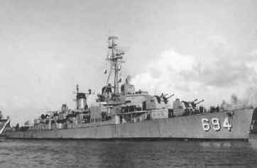
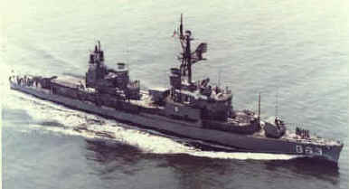
A BASILONE class destroyer,
she displaced 3460 tons when full, was 390 feet long, had 60,000 SHP,
General Electric Geared Turbines powering 2 screws to a maximum speed of
36.8 knots.
|
|
|
|
|
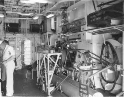
| Above, this is the Starboard side of the Flight deck of the WILSON- the area at right is the Deck control station for the DASH. Here the DASH Controller would launch DASH for hand-off to the CIC (combat information center) operator. | Above, here we are looking inside the Hangar where QH-50C, DS-1138 is stowed with the removable work stand attached to the aircraft. This view is Starboard, looking forward. Note the Blade containers at top-right. |
|
|
|
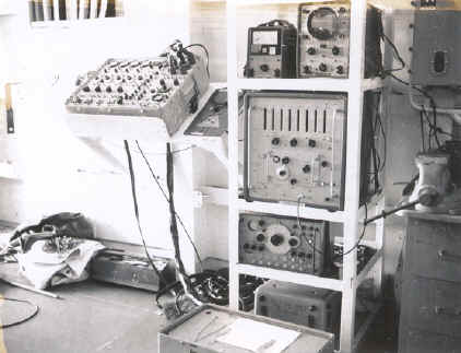
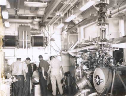
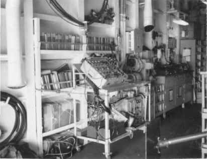
| Above, the "Library of Manuals" can be seen behind a piece of equipment called the AN/ASM-103 Automatic Flight Control Field Analyzer. The manuals required for the aircraft equipment as well as ship-based equipment exceeded over 30 volumes! | Above is the transmitter room on the WILSON. The DASH equipment begins at far right- that is the twin installation of the AN/URW-14A Radio Transmitting Sets, and below that is the PP-2288/SRW-4 Power Supply and twin set of KY-342/SRW-4C Audio Frequency Coders. Left of that assembly is the Target Control System Test Set (AN/SRM-5). |
|
|
|
|
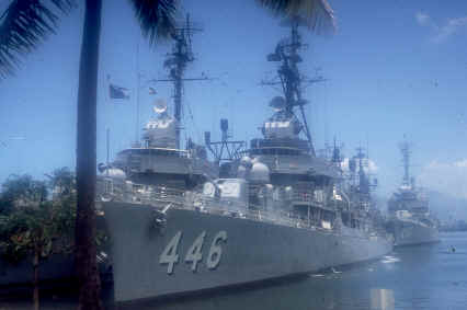
An ALLEN M. SUMNER class destroyer,
she displaced 3218 tons when full, was 376 feet 6 inches long, had 60,000 SHP,
General Electric Geared Turbines powering 2 screws to a maximum speed of
36.5 knots.
|
|
|
|
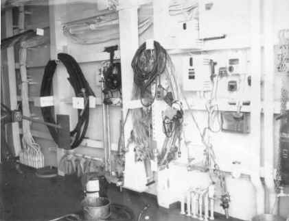
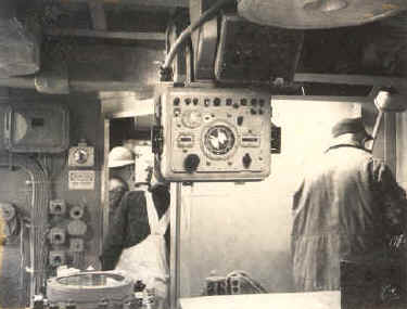
| This is the view of the INGRAHAM's Combat Information Center or CIC for the DASH system. At top with the dial, is the Transmitter Control (C-3313/SRW-4C) and at lower right, with all the switches, is the Transmitter Control (C-2804 / SRW-4). The C-3313 control allowed the CIC Pilot/Drone controller to fly the aircraft (after transfer was made from the deck control station) to the distant sonar contact using the ships radar to track the aircraft. The C-2804 control allowed the CIC to select which antenna to use (fore or aft), which transmitter to use and to switch between deck or CIC control of the QH-50C Drone. | In the INGRAHAM's transmitter room, the aft end shows the two Target Control System Test Sets: On the left is the AN/SRM-3 and on the right is the AN/SRM-5. The SRM-3 Test set allowed the ship's DASH personnel to test performance of the target control system. The SRM-5 allowed the ship's DASH personnel to simulate signals used to control the QH-50C Drone (DASH) and diagnose any faults within the system before flying the aircraft. Each DASH ship received these test sets. An additional test set, a AN/PSM-4 Multimeter was also used to perform continuity tests. |
|
|
|
Above is the Block Diagram for the Target Control System AN/SRW-4C which controlled the DASH system on Board U.S. Naval FRAM Destroyers |
|
U.S.S. STEINAKER (DD-863) |
|
A GEARING class destroyer,
she displaced 3460 tons when full, was 390 feet 6 inches long, had 60,000 SHP,
General Electric Geared Turbines powering 2 screws to a maximum speed of
36.8 knots. Her crew numbered 336.
|
|
|
|
|
|
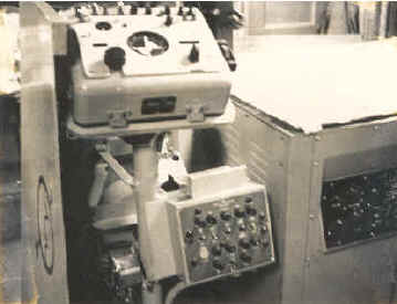
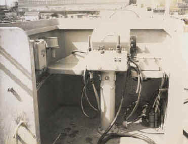
Above, the Transmitter Control (C-3313 / SRW-4C) as installed on the STEINAKER. The C-3313 control was designed to operate the QH-50 DASH beyond visual contact distances. Controls were provided for three proportional channels and six on-off channels. A fourth channel "Lateral Trim" was available but not used. |
Above is the Deck Control station on the STEINAKER. The item with the "stick" is the Transmitter Control (C-3314/SRW-4C). This control provided the control functions to govern the flight of the QH-50 Drone from lift-off from the deck to 100 yards astern the ship where CIC would take over. Upon return, CIC would release command of the drone and the Deck Controllers would land the aircraft from this station. |
|
|
|
|
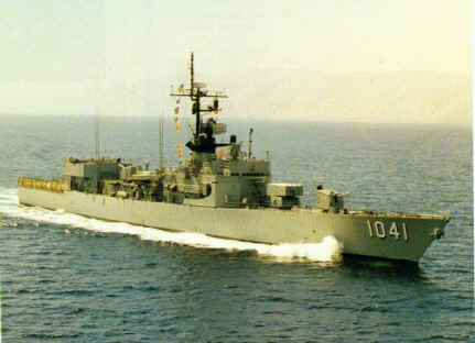
A BRONSTEIN class destroyer
escort, USS BRONSTEIN displaced 2650 tons when full, was 371 feet 6 inches long, had 20,000 SHP,
Foster-Wheeler boilers with one De Laval geared turbine powering 1
screw to a maximum speed of 26 knots. Her crew numbered 216.
|
|
|
|
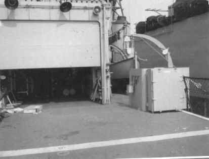
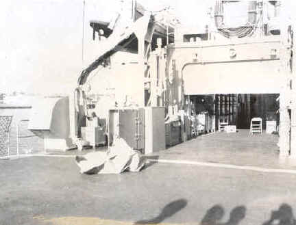
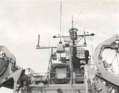
| Above, is the BRONSTEIN's flight deck. The Flight Deck Station was the guiding activity for the QH-50 drone during visual portions of the flight. On the BRONSTEIN, the deck control station is at left or on the port side. While BRONSTEIN was built this way, others destroyers that were FRAM'd to receive a flight deck and control station also involved the placement of the deck control station on the right side or Starboard side. Almost EVERY FRAM installation/reconstruction was a custom installation due to the various classes of ship involved as well as differing manufacturers and the various ship yards performing the FRAM modifications. | As on other FRAM Destroyers and Destroyer Escorts, the mast assembly changed during FRAM as the DASH antenna's were installed. There were two antenna's- one for the fore (forward) and one for the aft (rear) of the ship. On the Transmitter control panel at the deck and CIC stations, the operator had the capability of selecting which antenna to use, relative to the Drone's position, to maintain maximum control capability of the Drone. |
|
|
|
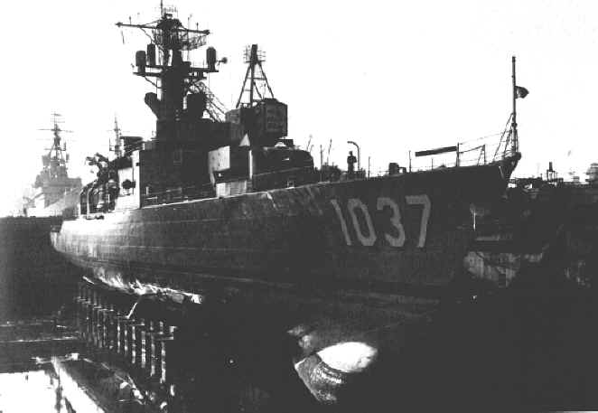
Above, the USS Bronstein (DE-1037) in dry dock at San Diego showing the massive SQS-26 bow mounted sonar being installed around December 5, 1963. This sonar gave the detection range required for the DASH weapon system to be used to its designed ASW range- out to 20,000 yards (over 11 miles from ship).
In the summer of 1967, USS McCLOY returned to
dry dock to receive the SQS-26 AX (major retrofit).....both she and
BRONSTEIN went straight from SQS-26 to SQS-26 AX(R) without getting the AX
variant. With the history of BRONSTEIN above, the USS McCLOY (the only other BRONSTEIN class DE) (seen at left) suffered the same fate: After she was reclassified as a Frigate (FF-1038) on June 30, 1975, she was decommissioned on December 14, 1990, stricken December 17, 1990 and sold to Mexico on October 1, 1993 (along with BRONSTEIN) and renamed "NICHOLAS BRAVO (E-40)". As of August 2001, she still serves in the Mexican Navy. |
|
|
|
A DEALEY class destroyer
escort,
she displaced 1877 tons when full, was 315 feet long, had two Foster-Wheeler boilers with one De Laval geared turbine
generating 20,000 SHP which powered 1
screw to a maximum speed of 27 knots. Her crew numbered 173.
|
|
|
|
|
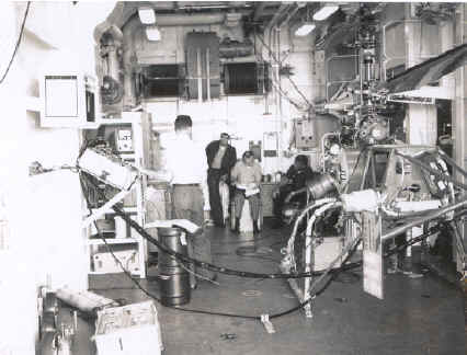
| An interesting view of checking out the FRAM installation on the EVANS for the Drone handling equipment, with a QH-50 "Simulated Aircraft" to check the cable equipment used to assist the crew in hauling the Drone back into the hangar deck, on a rolling, pitching ship deck. Winches inside the hangar, mounted on the center-fore section wall were attached to the vehicle to pull it into the hangar. | Above, a Navy Officer points out a close tolerance between the QH-50 "Simulated Aircraft" and the Deck control station. The QH-50 "Simulated Aircraft" had a 45 gal drum for an engine, rough tube fuselage and wooden tail. However, it used actual landing gear to test the handling procedures. The simulated aircraft was vital to check the fit of the aircraft to the hangar's clearances and fit of the storage areas and supplies relative to the aircraft. |
|
|
|
|
A GARCIA class destroyer
escort,
she displaced 3560 tons when full, was 414 feet 6 inches long, had two
Foster-Wheeler boilers with one Westinghouse geared turbine generating
35,000 SHP which powered 1
screw to a maximum speed of 27.5 knots. Her crew numbered 247.
|
|
|
|
| Above, the view of the BRADLEY's deck control station shows the 3 principle components of that station: At left, the Transmitter Control C-2804/SRW-4 (small box with switches and lights), with the stick is the Transmitter Control C-3314/SRW-4C and above that is the Control Monitor C-4298/ASW-20. The Control Monitor provided the Deck Control Pilot the capability to initiate the start up of the QH-50's turbine engine, and to monitor the transmission, engine and on-board electrical power of the Drone prior to launch from the ship. After launch, the Deck Control Pilot could then set the "Drone Angle relative to the ship" before handoff to CIC. | The view of the dual AN/URW-14A Transmitting sets in the BRADLEY's Transmitter room. The actual transmitting function comprised two Audio Frequency Coder (KY-342/SRW-4C) units, two Radio Transmitting sets, RF Transmitting Line Switch (SA-631/SRW-4, Interconnecting Box (J-1052/SRW-4) and two UHF Circularly Polarized Antenna AT-781A/U units. Digital-type coding required either Transmitting Control (C-3313 or C-3314) be used to provide the coded input to the radio transmitting sets. If non-proportional-type coding was selected, the internal coder in the radio transmitting set will provide requisite inputs to the transmitter. |
|
|
A FLETCHER class destroyer,
she displaced 2924 tons when full, was 376 feet 5 inches long, had 60,000 SHP,
General Electric Geared Turbines powering 2 screws to a maximum speed of
38 knots. Her crew numbered 273.
|
|
|
|
|
| Above is a view of the ONLY test set equipment located in the DASH hangar. This view is portside-mid section of the RADFORD's DASH Hangar. The test set at left is the AN/ASM-103 Automatic Flight Control Field Analyzer. The equipment below the AN/ASM-103 was the control monitor, transmitter control and decoder test sets. |
Above, a technician on the RADFORD, has hooked up the AN/ASM-103 to QH-50C, DS-1199, to test the avionics. The AN/ASM-103 was designed to be directly connected to AFCS connector on the QH-50 drone and, with the Rotary servo actuator powered up with an auxiliary drive electric motor, analyze the complete avionics and flight control system of the drone and detect problems that needed adjustment. The AN/ASM-103 did this by simulating signals from the ship-based control system and then measured the avionics system response. A complete functional test using this piece of test equipment was required before a flight!
|
|
|
|
| This picture on the RADFORD (above-left) provides an idea of the limited space provided for these aircraft and why their 20' rotor diameter and compactness afforded by the coaxial rotor system made DASH possible. The left picture was taken standing AGAINST the port wall, looking forward and starboard. With each Destroyer having a twin DASH installation (2 aircraft per ship), space was tight between the aircraft (see right photo). Note the winches at the forward wall for the cable-retrieval system when rolling-pitching seas made Drone handling difficult. This system was later abandoned due to easier ground handling gear and top-weight considerations. | Above shows the starboard side of the middle of
the DASH hangar on RADFORD. The black hose is for fueling of the aircraft
(note nozzle on the end). Also hanging on the wall are the cable
assemblies for the winch arrangement. After a ASW (anti-submarine warfare)
flight and removal of the twin MK-44 homing torpedoes to the side weapons
locker, the QH-50 was relatively easy to move with its two ground handling
wheels placed at the center of its gravity on the bottom landing gear
skid.
|
|
|
|
|
Below is the second verse to Anchors Aweigh........ We felt this was a good way to end this page, of Navy ships and aircraft and men of a time, long gone. |
|
Stand, Navy, out to sea, Fight our battle cry;
|
|

![]()
![]()


![]()


![]()
|
The name "Gyrodyne" in its stylized
form above, is the Trademark of and owned by the Gyrodyne Helicopter Historical
Foundation; unauthorized use is PROHIBITED by Federal Law. All Photographs, technical specifications, and
content are herein copyrighted and owned exclusively by Gyrodyne Helicopter
Historical Foundation, unless otherwise stated. All Rights Reserved
©2013. |
 It took an incredible level of commitment on the U.S. Navy's part
to develop and field CNO Admiral Arleigh Burke's dream of flying remote control
helicopters from his beloved WW II era destroyers. It was the only way to make those
vessels have the capability of countering the strategic threat the Russian
submarine force was forecasted to pose with long range torpedoes in the 1960's.
It took an incredible level of commitment on the U.S. Navy's part
to develop and field CNO Admiral Arleigh Burke's dream of flying remote control
helicopters from his beloved WW II era destroyers. It was the only way to make those
vessels have the capability of countering the strategic threat the Russian
submarine force was forecasted to pose with long range torpedoes in the 1960's. people interested in the modifications to the Navy ships
themselves, to allow DASH to function. It simply was not the placing of an
aircraft on a new flight deck. A 5" gun turret needed to be removed and a
flight deck built (see USS Bronstein (DE-1037) at left,
built from scratch with the FRAM
improvements) in its place, weapons storage lockers for
the MK-44 torpedoes, wire runs to the CIC station and back to the new deck
control station, new antennas, adding of a hangar, and the installation of a new
long range sonar system - All these things had to be added to a ship for DASH to fly
and be effective. However, the job was time consuming: Some FRAM modifications took some ships out of action for
more than a year!
people interested in the modifications to the Navy ships
themselves, to allow DASH to function. It simply was not the placing of an
aircraft on a new flight deck. A 5" gun turret needed to be removed and a
flight deck built (see USS Bronstein (DE-1037) at left,
built from scratch with the FRAM
improvements) in its place, weapons storage lockers for
the MK-44 torpedoes, wire runs to the CIC station and back to the new deck
control station, new antennas, adding of a hangar, and the installation of a new
long range sonar system - All these things had to be added to a ship for DASH to fly
and be effective. However, the job was time consuming: Some FRAM modifications took some ships out of action for
more than a year! 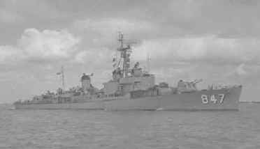


 The BRONSTEIN (operated in Pacific Fleet) and sister ship USS McCLOY (DE-1038)
(operated in Atlantic Fleet) were both originally
built with the original SQS-26 bow mounted sonar which was included as an
update for other older destroyers undergoing FRAM work. The Bronstein
class of Destroyer Escorts were the smallest ships that could carry the
sonar when they were commissioned in 1963 and in fact were purpose-built
to be test beds for the installation. They represented a halfway step between the
small Dealey class and the larger Garcias class of Destroyer Escorts. The
Bronstein class incorporated the same 600 PSI engineering plant as the Dealeys, but
interestingly even though they were considerably larger, they were faster as well, probably because the
large bow-mounted sonar gave them a more efficient hull form. The original
systems were miserably unreliable and the SQS-26 AX installed in the Garcias wasn't much better.
The BRONSTEIN (operated in Pacific Fleet) and sister ship USS McCLOY (DE-1038)
(operated in Atlantic Fleet) were both originally
built with the original SQS-26 bow mounted sonar which was included as an
update for other older destroyers undergoing FRAM work. The Bronstein
class of Destroyer Escorts were the smallest ships that could carry the
sonar when they were commissioned in 1963 and in fact were purpose-built
to be test beds for the installation. They represented a halfway step between the
small Dealey class and the larger Garcias class of Destroyer Escorts. The
Bronstein class incorporated the same 600 PSI engineering plant as the Dealeys, but
interestingly even though they were considerably larger, they were faster as well, probably because the
large bow-mounted sonar gave them a more efficient hull form. The original
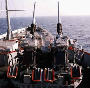
systems were miserably unreliable and the SQS-26 AX installed in the Garcias wasn't much better. 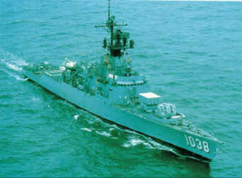 and
the crew couldn't fire their forward 3"/50 (twin) Mk 33 guns (seen
above-right) without dropping
the sonar off the line. The preceding top of the line system was the SQS-23,
but the SQS-26 did NOT evolve from the -23.....it was a completely new design to take advantage of bottom-bounce and convergence zone modes.
and
the crew couldn't fire their forward 3"/50 (twin) Mk 33 guns (seen
above-right) without dropping
the sonar off the line. The preceding top of the line system was the SQS-23,
but the SQS-26 did NOT evolve from the -23.....it was a completely new design to take advantage of bottom-bounce and convergence zone modes.