|
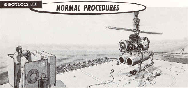
PREPARATION
FOR FLIGHT
The
drone should be spotted on the launch area and secured to the deck with the
pre-launch tie down device, which is equipped with a remotely actuated release (see figure 3
below in “Description” section, item 33).
FLIGHT
RESTRICTIONS

Wherever
reference is made to "true airspeed", refer to the airspeed calibration data
in “Performance Data” section for the command readout required to produce
the desired true airspeed of the drone.
MISSION PLANNING
Determine the drone gross weight with full fuel load. Obtain pertinent weather
information, including ambient conditions. Determine which transmitter-coder
combination and which antenna is to be used for the mission. Determine the
mission envelope by referring to the performance data in Appendix 1.

The elapsed time indicators on both the control monitor
and CIC control should be used to register total engine running time for each
mission. The timer on the control monitor starts when the engine starting cycle
is initiated, and should not be reset to 0 after the engine has started. The
timer on the CIC control should be reset to 0 when the deck controller initiates
the engine start cycle so that both timers are synchronized.
Check
the number and type of weapons to be carried, weapon depth settings, and weapon
turning direction.
Search
the target control system frequency for interference.
Check
the operation of the interphone system between the deck and CIC control
stations. Check the operation of the interphone system between the control
stations and the target control system test set monitoring room (DASH
transmitter room).
COMMAND
MONITORING AND RECORDING
Throughout
all drone missions, continuous voice communication should be maintained between
the drone controller, deck or CIC, and the technician monitoring the Audio
Frequency Decoder KY-433/SRM (BCD-24) (part of Target Control System Test Set
AN/SRM-4). The controller must announce each command or change of command and
the technician must affirm a satisfactory decoder readout or report a discrepant
readout. The technician must also report any deviation from a steady state
command.
During
the entire drone mission, except during launching and landing, the technician
should maintain a continuous record of all new commands and resultant test set
readouts, together with the mission time or real time at which made.
In
the event of deterioration of the data link, refer to the "Emergency
Procedures section". Attempts should be made to return the drone to the ship and land
it on the deck if possible.
PREFLIGHT
CHECK
Check
the preflight inspection completion report to determine drone status. Make
certain that the preflight avionics functional check has been completed (MRC J-
54 R- 2). Check the date of the last weekly avionics functional check (MRC J-54
W-2). Check the date of the last target control system test and inspection (MRC
J-31 W-1).
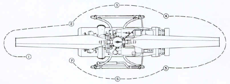
EXTERIOR INSPECTION
Perform an exterior inspection as indicated in below
figure 1
|
|
|
1.
GENERAL.
a.
Engine air inlet cover and screen and blade restrainers removed.
b.
Hold-down cable secure and taut; cable connector and receptacle
mated.
c.
Deck handling gear clear of drone. d.
Fuel and oil leaks on deck.
e.
All electrical connectors for proper connection.
2.
RIGHT FRONT.
a.
Arming solenoid and bracket for security; cable for signs of
chafing.
b.
Starter-generator and cables for security and signs of chafing.
c.
Ignition unit for security; cables for signs of chafing.
d.
Fuel filter and fuel lines for security and leaks.
e. Oil filter and oil lines
for security and leaks.
f. Engine exhaust outlet
cover removed; exhaust deflectors for proper angular position.
g.
Engine electrical connector and bracket for security; cable for
security and signs of chafing.
3.
RIGHT SIDE.
a.
Gust locks for engagement with upper and lower rotor hub
assemblies.
b.
Rigging pins removed from servo actuator.
c. Control locks engaged.
d.
Barometric altitude control and roll and pitch gyroscope for
security.
e.
Weapon for proper installation; release solenoid cable for
security.
f.
Suspension band release wires for proper rigging.
g.
Bomb shackle safety pin removed (for intentional weapon drop or
emergency weapon jettison).
h.
Deck handling gear removed from skid.
4.
RIGHT REAR.
a.
Fuel tank for security and damage; fuel line for security and
leaks.
|
b.
Emergency flotation system for security, damage, and proper
pressurization; quick release pin removed from hydrostatic release
assembly; spring keeper installed.
c. Torpedo air
stabilizer and static line for security; safety clamp removed.
d.
Avionic panel for security and damage.
5. LEFT
REAR.
a.
Fuel tank for security, damage, and proper quantity of fuel; filler
cap for security, vent plugs removed.
b.
Torpedo air stabilizer and static line for security; safety clamp
removed.
c.
Orientation light switch as required.
6.
LEFT SIDE
a.
Transmission housing for leaks; oil filler cap for security; oil
level sight gage for cracks, proper oil level, and security.
b.
Gyroscope control box N-S and LAT controls for proper setting.
c.
Rigging pins removed from servo actuator.
d.
Weapon for proper installation; release solenoid cable for
security.
e.
Suspension band release wires for proper rigging.
f.
Bomb shackle safety pin removed (for intentional weapon drop or
emergency weapon jettison).
g.
Deck handling gear removed from skid.
h.
Antenna cables and connectors for security; antenna actuator
retaining chain removed.
7.
LEFT FRONT.
a.
Power turbine limiter for security and oil leaks; air line to fuel
control unit for security.
b.
Engine exhaust outlet cover removed; exhaust deflector for proper
angular position.
c.
Fuel control unit for security and fuel leaks. d.
Engine oil sump for proper quantity of oil;
filler cap and
dipstick for security; oil lines for security and leaks.
e.
Orientation light and arming solenoid for security; cables for
signs of chafing.
|
PRELIMINARY
CONTROL SETTINGS
Set
the shipboard guidance controls at the deck station as follows:
Make
certain that any drone undergoing test in the hangar has its decoder address
selector set at a different address from the drone being flown, so that it will
not respond to flight commands.
1.
Control Monitor:
a.
MASTER switch--OFF.
B. TRANSFER switch- -DRONE.
c. AUTO-PURGE-MANUAL
switch--MANUAL.
d. GYRO switch--OUT.
e. DRONE ANGLE REL TO SHIP
pointer--aligned with drone (pointer indicates engine air inlet).
f. ELAPSED TIME indicator--60.
2.
Transmitter Control (Deck):
a.
HV switch--OFF.
b. CODER switch--EXTERNAL.
c. KEYED CARRIER-CONSTANT CARRIER
swit6h--CONSTANT CARRIER.
d. ANT. SEL switch--STBD.
e. XMTR 1-XMTR 2 switch--XMTR 1.
f. PWR switch--ON.
(Wait one minute, minimum.)
g. HV switch--ON.
3.
Deck Control:
a.
CRUISE-MANUV switch--CRUISE.
b. MEMORY-STATION switch--STATION.
c. WEAPONS JETTISON switch--off.
d. SPARES ON switches--off.
e. ENG OFF switch--on.
f. CABLE REL switch--off.
g. ADDRESS knob--at drone address.
h. PWR ON switch--on.
i. ALTITUDE knob--at 000 readout.
j. AIRSPEED knob--at 00 FWD
readout.
k. HEADING pointer--aligned with
drone.
4.
Turn motor-generator output circuit breakers off.
5. Connect the AFC set and engine
umbilical cables.
6. Turn motor-generator output
circuit breakers on.
7. Turn control monitor MASTER
switch to ON and turn TRANSFER switch to AUX.

When
Telemetric Data Transmitter T-1014/AKT-20 is installed and energized, a
radiation hazard exists within 2 feet of Antenna AS-1886/AKT-20.
8.
Press RESET switch to return the ELAPSED TIME indicator to 60.
9.
Monitor auxiliary generator output voltages by turning the VOLTAGE
MONITOR knob to positions 1 through 9. The meter should indicate within the
acceptable band at each position, except that on position 1, the indication may
be to the left of center. After monitoring voltages, leave the knob set at
position 6 (40 volts DC from the airborne power supply).
Make
certain that the VOLTAGE MONITOR meter pointer remains in the acceptable area on
the meter at each position.
Set the shipboard guidance controls at CIC as
follows:
1.
Transmitter Control (CIC):
a.
CODER switch--EXTERNAL.
b. KEYED CARRIER - CONSTANT CARRIER
switch--CONSTANT CARRIER.
c. ANT. SEL switch--STBD.
d. XMTR I - XMTR 2 switch--XMTR
1.
e. PWR switch--OFF.
f. HV switch--ON.
The
deck station transmitter control (C-2801/SRW-4) PWR switch must be turned on
before the CIC transmitter control (C-2804/SRW-4) PWR switch in order to provide
initial command authority for the deck drone controller. The CIC transmitter
control PWR switch should remain in the OFF position until just prior to the
transfer of command.
2.
CIC Control:
a.
WEAPON ARM switch--off.
b. SPARES ON switches--off.
c. MEMORY-STATION
switch--MEMORY.
d. WEAPON RELEASE
switches--off.
e. ADDRESS knob--at drone
address.
f. PWR ON switch--on.
g. ALTITUDE knob--at 000 readout.
h. AIRSPEED knob--at 00 FWD
readout.
i.
HEADING pointer--same true heading as at deck station.
j. ELAPSED TIME indicator--running.
Make
certain that the airspeed readout at both deck station and CIC is at 00 FWD
(the right-hand side of the AIRSPEED window). If 00 shows at
the AFT (left) side of the window, it is equivalent to a 100 knot
aft airspeed command!
BEFORE
STARTING ENGINE
Observe
the following precautions before starting the engine:
Refer to figure 2 for danger areas and ground clearances.
Make
certain that the ADS OPERATE lights on both deck and CIC transmitter controls
are on and that both engine and AFC set umbilical cables are connected.
Make
certain that the ALT SYNC and GYRO SLAVING meters are nulled. Pinch the rubber
tube near its point of attachment to the barometric altitude control mounting
bracket. The pointer of the ALT SYNC meter should oscillate slightly as the tube
is pinched and released. If the pointer does not oscillate, the drone should not
be flown until the discrepancy is corrected.
The
GYRO SLAVING meter should indicate within the green band or oscillate uniformly
and equally beyond each side of the green band (not hitting the stops) before
power is transferred to the airborne generator.
Make certain that the cyclic
control locks are engaged.
Make
certain that the launching area is clear of personnel and equipment.
STARTING ENGINE (AUTOMATIC SEQUENCE)
Allow a 2
minute cooling period between each 30 second cranking cycle. After cranking for
a total of 90 seconds, allow the starter- generator to cool for 10 minutes
minimum.
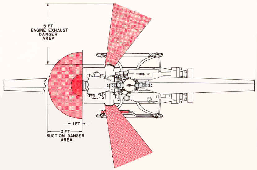
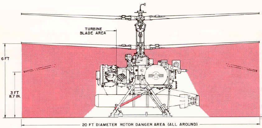
DANGER AREAS AND GROUND CLEARANCES; Figure 2
|
|
|
|
|
|
1. DO NOT WALK UNDER ROTORS WHEN
THEY ARE TURNING.
2. IN THE AREA 1 FT. IN FRONT OF
THE ENGINE INTAKE, LOOSE ARTICLES WILL BE SUCKED INTO THE ENGINE WITH THE
SCREEN OFF.
3. IN THE AREA 3 FT. IN FRONT OF
THE ENGINE, CLOTH WILL BE SUCKED INTO THE ENGINE WITH THE SCREEN OFF.
4. HEAT FROM ENGINE EXHAUST CAN
CAUSE SEVERE BURNS.
5. RADIATION HAZARD EXISTS WITHIN 2
FEET OF ANTENNA WHEN TELEMETRY IS OPERATING.
|
STARTING
ENGINE (AUTOMATIC SEQUENCE) - CONTINUED
1.
Set AUTO-PURGE-MANUAL switch to AUTO.
2.
Momentarily depress the AUTO START button.
3.
After the engine has been running for 6 to 9 seconds, check for an
indication of rising exhaust
gas temperature on the EXH TEMP meter of the control monitor.
4.
Check the engine OIL PRESS indicator on the control monitor. If, after 25
to 35 seconds of engine rotation, there is no engine oil pressure indicated,
shut down the engine. If the TRANSMISSION PRESS indicator light fails to go out
within 25 to 35 seconds of the engine start, shut down the engine. If the
transmission oil temperature light goes on, shut down the engine.
If
combustion occurs but the engine fails to accelerate to flight idle rpm,
stop the engine immediately using data link, to prevent damage to the engine.
During
the starting cycle and until the rotor speed is stabilized, the
exhaust gas temperature should not exceed 1200º F. Refer to the "Performance
Data" section for charts of stabilized exhaust gas versus ambient
temperature.
5.
Observe the % ROTOR RPM meter. If the pointer moves past a point
approximately 1/16 inch beyond the extreme right-hand graduation of the scale
(approximately 115%), press the control monitor engine STOP switch immediately.
After the TRANSFER switch has been turned to DRONE, use the deck control ENG OFF
switch; do not use the control monitor engine STOP switch.
6.
Increase altitude command until COLLECTIVE FOLLOW UP POSITION meter on the
control monitor indicates 10.
PURGING ENGINE
After a start failure and prior to a new
start attempt, the engine must be purged of accumulated fuel. To purge the
engine, proceed as follows:
1. Set
AUTO-PURGE-MANUAL switch on control monitor to PURGE position.
2. Momentarily depress
AUTO START switch. The engine will purge itself and automatically stop after 30
seconds.
3.
If the engine does not stop after 30 seconds, depress STOP switch.
Allow
a 2 minute cooling period between each 30 second cranking
period.
After cranking for a total of 90 seconds, allow the starter to cool for 10
minutes.
MANUAL
ENGINE START
Observe
the same precautions during a manual engine start as would be observed during an
automatic engine start.
1.
Set AUTO-PURGE-MANUAL switch on the control monitor to MANUAL.
2.
Move the START-PREHEAT switch to START and hold.
3.
Wait 4 to 6 seconds, and momentarily depress the FUEL ON button.
4.
Continue to hold the START-PREHEAT switch in the START position until the
ELAPSED TIME indicator reads 25 to 30 seconds, or until the % ROTOR RPM meter
pointer enters the green area, whichever occurs first.
5.
Release the START-PREHEAT switch.
6.
Repeat steps 3 through 6 of automatic start procedure.
DRONE CONTROL SYSTEM
PRELAUNCH TESTS
Prior to launching
the drone, the operation of the flight control system and the data link should
be checked while the drone is tied down on the deck. The tests to be performed
are listed in figure 3.
In performing the
pre-launch command tests, do not allow any of the follow-up position meters to
remain at full scale deflection any longer than is necessary; under no
circumstances, more than an absolute maximum of 3 seconds. Severe damage to the
magnetic clutches in the servo actuator may result if this limit is exceeded.
In performing the
pre-launch command tests, do not exceed 100 feet of altitude command.
If the ship changes
heading before the drone is launched, the heading card and pointer in the deck
control will remain fixed with respect to true north, creating a relative mis-
alignment between the pointer and the drone. The heading pointer on both deck
and CIC controls must be readjusted accordingly as soon as possible. When the
ship is maneuvering this must be monitored continuously and readjustments made
accordingly.
Make certain that
the % ROTOR RPM indicator pointer is between 95% and 110% before turning the
TRANSFER switch to DRONE.
If the cyclic
control locks do not disengage when the TRANSFER switch is turned to DRONE, do
not attempt to disengage them manually. Stop the engine by moving the ENG OFF
switch on the deck control in the direction of the arrow. If this fails to stop
the engine, return the TRANSFER switch to AUX and press the control monitor
engine STOP switch.
PREPARATION FOR TEST
Before starting the
pre-launch command tests set forth in figure 3, the following preparatory
steps must be accomplished.
1. With the TRANSFER
switch still at AUX (control locks engaged), turn the CRUISE-MANUV switch to
MANUV. Check for roll and pitch command response by moving the maneuver stick
slightly. The ROLL and PITCH FOLLOW UP POSITION meters should indicate a small
deflection in the appropriate direction. Leave the CRUISE-MANUV switch at MANUV.
2. Turn
MEMORY-STATION switch to MEMORY. Turn the TRANSFER switch to DRONE. The AUX
light should go out and the DRONE light should go
on. Turn MEMORY-STATION switch to STATION. If necessary, readjust the
altitude command to produce a COLLECTIVE FOLLOW UP POSITION meter indication of
10. Record the altitude readout. This setting is referred to hereinafter as
"10% collective. "
If
the VOLTAGE MONITOR meter pointer does not register within or drifts out of the
acceptable area, stop the engine immediately by moving the deck control ENG OFF
switch in the direction of the arrow.
3.
Check for control lock disengagement by moving the maneuver stick slightly in
pitch and roll to produce approximately 10 percent displacement on the related
FOLLOW UP POSITION meter.
If
10 percent displacement cannot be achieved (due to failure of the control locks
to disengage), stop the engine immediately by moving the deck control ENG OFF
switch in the direction of the arrow.
4. Turn the VOLTAGE
MONITOR knob to positions 1 through 9. The meter pointer should indicate within
the acceptable area on the meter at each position, except position 1 which may
indicate to the left of center.
5. Turn the VOLTAGE
MONITOR knob to position 6. The pointer should remain in the acceptable area.
6.
Proceed with the prelaunch command tests shown in figure 3. Control response
indications should follow the command inputs without jerkiness or discontinuity.
Make
certain that the VOLTAGE MONITOR knob is at position 6.
Figure 3; Prelaunch Command Tests
|
Procedure
|
Result
|
1. Slowly displace the maneuver stick fully in a plane parallel to the
orientation of the HEADING pointer, in the direction indicated by the
pointer
|
The PITCH FOLLOW UP POSITION meter should
indicate 90 F minimum
|
2. Slowly displace
the maneuver stick fully in a plane parallel to the orientation of the
HEADING pointer, in the direction opposite to that indicated by the
pointer.
|
The
PITCH meter should indicate 90A minimum.
|
3. Slowly displace
the maneuver stick fully in a plane perpendicular to the orientation of
the pointer, in the direction to produce a left roll.
|
The
ROLL meter should indicate 90L minimum.
|
4. Slowly displace
the maneuver stick fully in a plane perpendicular to the orientation of
the pointer, in the direction to produce a right roll.
|
The
ROLL meter should indicate 90R minimum.
|
5.
Note the position of the HEADING pointer. Turn the HEADING knob
clockwise to displace the pointer 400 from the position noted.
|
The
YAW meter should indicate 100R. The upper tip brakes should be extended.
|
6.
Twist the maneuver stick counterclockwise to return the HEADING
pointer to the position noted in step 5.
|
The
YAW meter should return to 0 ±5. The upper tip brakes should
retract.
|
7.
Turn the HEADING knob counterclockwise to displace the pointer 40'
from the position noted in step 5.
|
The
YAW meter should indicate 100L. The lower tip brakes should be extended.
|
8.
Twist the maneuver stick clockwise to return the pointer to the position
noted in step 5.
|
The YAW meter should return to 0 ±5. The lower
tip brakes should retract.
|
9.
Turn the CRUISE-MANUV switch to CRUISE
|
There should be no movement of the FOLLOW UP
POSITION meters.
|
10. Set
airspeed readout at 30 AFT.
|
The PITCH meter should indicate 45A to 55A.
|
11. Return
airspeed readout to 00 FWD.
|
The PITCH meter should return to 0 ±5.
|
12.
Set airspeed readout at 30
FWD.
|
The PITCH meter should indicate 45F to
55F.
|
13.
Increase airspeed readout to
40 FWD.
|
The PITCH meter should indicate 52F to
64F.
|
14.
With airspeed readout at 40 FWD, increase altitude command
to 100 feet.
|
The
COLLECTIVE meter should indicate 20 to 25.
|
15. Turn the MEMORY-STAT ION switch to MEMORY.
|
There
should be no movement of any of the FOLLOW UP POSITION meters.
|
16.
Vary airspeed, altitude, and heading commands, then return
them to their previous settings.
|
There
should be no movement of any of the FOLLOW UP POSITION meters.
|
17.
Turn the CRUISE-MANUV switch to MANUV, displace the maneuver stick in
random directions, then return the switch to CRUISE.
|
There
should be no movement of any of the FOLLOW UP POSITION meters.
|
18. Turn the MEMORY-STATION switch to STATION.
|
There
should be no movement of any of the FOLLOW UP POSITION meters. The PITCH
and COLLECTIVE meters should remain at the indications noted in steps 13
and 14.
|
19. With airspeed and altitude commanded as in steps 13 and 14,
turn the deck transmitter control HV switch to OFF.
|
The
PITCH meter should indicate 0 ±5 within 14.5 ± 4. 5 seconds. The
COLLECTIVE meter should remain at the indication noted in step 14.
|
20. Return the HV switch to ON.
|
The
PITCH meter should return to its previous indication within 3. 5 ±1. 5
seconds.
|
21. Turn the MEMORY-STATION switch to MEMORY.
|
There
should be no movement of any of the FOLLOW UP POSITION meters.
|
22. Synchronize the CIC control airspeed, heading, and altitude
settings with the deck station. Turn the CIC transmitter control (C-
2804/SRW-4) PWR switch to ON.
|
None
|
23. Turn the deck transmitter control (C-2801/ SRW-4) PWR switch to
OFF and leave it in that position.
|
Control
is transferred from deck to CIC. There should be no movement of any of the
FOLLOW UP POSITION meters.
|
24. Turn CIC MEMORY-STATION switch to STATION.
|
There
should be no movement of any of the FOLLOW UP POSITION meters.
|
25.
Return the altitude readout to "110% collective, " previously
recorded and return airspeed readout to 00 FWD.
|
The
COLLECTIVE meter should indicate 10. The PITCH meter should indicate 0 ±5.
|
26.
Note the position of the CIC HEADING pointer. Turn the HEADING knob
clockwise to displace the pointer approximately 5' from the position
noted.
|
The
YAW and ROLL meter pointers should deflect toward the right.
|
27. Return the
pointer to its original position.
|
The
YAW and ROLL meters should return to 0 +5.
|
28.
Turn the HEADING knob counterclockwise to displace the pointer
approximately 5' from the position noted in step 26.
|
The
YAW and ROLL meter pointers should deflect toward the left.
|
29.
Return the pointer to its original position.
|
The
YAW and ROLL meters should return to 0 ±5.
|
30.
Repeat steps 10 through 16, 19, and 20 at CIC.
|
Same
as in steps 10 through 16, 19, and 20.
|
31.
Synchronize the deck control airspeed, heading, and altitude
settings with the CIC settings. Turn the deck transmitter control
(C-2801/SRW-4) PWR switch to ON.
|
None.
|
32.
Turn the CIC transmitter control (C-2804/ SRW-4) PWR switch to OFF
and leave it in that position.
|
Control
is returned to the deck station. There should be no movement of any of the
FOLLOW UP POSITION meters.
|
33.
Turn the deck MEMORY-STATION switch to STATION.
|
There
should be no movement of any of the FOLLOW UP POSITION meters.
|
34.
Return the deck altitude readout to " 10% collective" and
return airspeed readout to 00 FWD.
|
The
COLLECTIVE meter should indicate 10. The PITCH meter should indicate 0 ±5.
|
35.
Turn the CRUISE-MANUV switch to MANUV. Apply pitch, roll, heading,
and altitude commands at the deck station to recheck the data link.
|
The
FOLLOW UP POSITION meters should respond proportionally and in the proper
direction.
|
36.
Turn the MEMORY-STATION switch to MEMORY and turn the deck
transmitter control ANT. SEL switch to PORT. Return to STATION and apply
control commands.
|
The
FOLLOW UP POSITION meters should respond proportionally and in the proper
direction.
|
37.
Turn the MEMORY-STATION switch to MEMORY and turn the deck
transmitter control transmitter switch to XMTR 2. Return to STATION and
apply control commands.
|
The
FOLLOW UP POSITION meters should respond proportionally and in the proper
direction.
|
38. Turn the
MEMORY-STATION switch to MEMORY and return the deck transmitter control
ANT. SEL switch to STBD. Return to STATION and apply control commands.
|
The
FOLLOW UP POSITION meters should respond proportionally and in the proper
direction.
|
39. Turn the
MEMORY-STATION switch to MEMORY and return the deck transmitter control
transmitter switch to XMTR 1. Return to STATION and apply control
commands.
|
The
FOLLOW UP POSITION meters should respond proportionally and in the proper
direction.
|
40. Turn the GYRO switch to IN.
|
The
PITCH, ROLL, and YAW meters should respond to any pitch, roll, and yaw of
the ship in the direction opposite to the direction of ship motion.
|
PREPARATION FOR LAUNCHING
The manner in which
the drone is launched from the deck is dependent upon the direction Of the
relative wind. The maneuver stick should be deflected in the direction toward
the relative wind, regardless of drone heading, so that, as the drone lifts off
the deck, it will hover over the deck. Thus, its "airspeed" will be
equal to the velocity of the relative wind. This airspeed must be maintained
until the drone is clear of the ship, then increased as the drone climbs out.
When
using the maneuver stick in flight, avoid prolonged large
displacements. For all normal flight operations in the maneuver mode, a maximum
of approximately 30 percent of maneuver stick displacement from neutral should
be adequate.
Completion of the
prelaunch command tests listed in figure 3 chart, above, will confirm drone
readiness for launching.
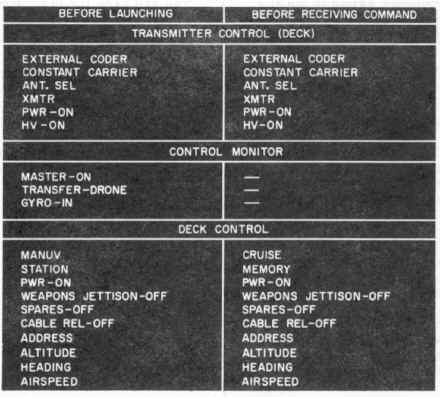
In order to assure
that the controls and switches are in their proper positions, the left-hand
column of the Deck Controller's Check List (figure 4-at
bottom) should be checked immediately before launching. The check to be
made for each item is listed below. The applicable controls and switches should
be synchronized between deck and CIC prior to launch and transfer. (The
explanation
of the right-hand column of figure 4 appears under the paragraph heading
RETURNING COMMAND TO DECK in this section.)
Figure 4; Deck Controller's Check List
|
DECK CONTROLLER'S CHECK
See figure 4, Left-hand column
| Transmitter Control (Deck) |
|
1.
CODER switch at EXTERNAL.
2. KEYED CARRIER-CONSTANT CARRIER switch at CONSTANT CARRIER.
3. ANT. SEL switch as directed.
4. XMTR 1 - XMTR 2 switch as directed.
5. PWR switch at ON.
6. HV switch at ON.
|
| Control Monitor |
|
1.
MASTER switch at ON.
2. TRANSFER switch at DRONE.
3. GYRO switch at IN.
|
| Deck Control |
|
1.
CRUISE-MANUV switch at MANUV.
2. MEMORY-STATION switch at STATION.
3. PWR switch on.
4. WEAPONS JETTISON switch off.
5. SPARES switches off.
6. CABLE REL switch off.
7. ADDRESS switch at drone address.
8. ALTITUDE readout at "10% collective".
9. HEADING
pointer aligned with drone heading.
10.
AIRSPEED readout at 00 FWD.
|
Make
certain that the airspeed readout is at 00 FWD (the right-hand side of the
AIRSPEED window). If 00 shows at the AFT (left) side of the window, it is
equivalent to 100 knot aft airspeed command.
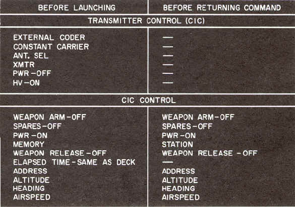
The left-hand column of the CIC Controller's Check List (figure 2-5) should be
checked before launching. The check to be made for each item is listed below.
(The explanation of the right-hand column of figure 5 appears under the
paragraph heading RETURNING COMMAND TO DECK in this section.)
Figure 5; CIC Controller's Check List
|
CIC CONTROLLER'S CHECK
See figure 5, Left-hand column
| Transmitter Control (CIC) |
|
1.
CODER switch at EXTERNAL.
2. KEYED CARRIER-CONSTANT CARRIER switch at CONSTANT CARRIER.
3. ANT. SEL switch same as at deck station.
4. XMTR switch same as at deck
station.
5. PWR switch at OFF.
6. HV switch at ON.
|
| CIC Control |
|
1.
WEAPON ARM switch off.
2. SPARES switches off.
3. PWR switch on.
4. MEMORY-STATION switch at
MEMORY.
5. WEAPON RELEASE switches off.
6. ELAPSED TIME indicator same as at deck station.
7. ADDRESS switch at drone address.
8. ALTITUDE readout same as at deck station.
9. HEADING pointer at same heading as at deck station.
10. AIRSPEED readout same as at deck station.
|
LAUNCHING THE DRONE
In
launching the drone from a rolling and/or pitching deck, the launch should be
made as the ship passes through an even keel attitude in roll, in the direction
into the relative wind, and at a stern high attitude in pitch.
The
remaining steps required to launch the drone are, in the order listed:
1.
Increase altitude command, by rotating the ALTITUDE knob, until the COLLECTIVE
FOLLOW UP POSITION meter indicates 15.
2.
Press UMBILICAL RELEASE switch. (The umbilical cables should disconnect.)
3.
Move ALTITUDE RATE switch up momentarily. (The tie down device should
disconnect.)
As soon as the tie down device falls to the deck, release the ALTITUDE RATE
switch and use the ALTITUDE knob and maneuver stick to keep the drone 5 to 10
feet over the launching spot for approximately 20 seconds. Using the maneuver
stick, move the drone away from the ship in the direction into the relative
wind. Twist the maneuver stick as required to head the drone fuselage into the
relative wind while maintaining the drone flight path into the relative wind.
Make certain that the antenna is in its downward position.
Do
not allow the drone to drift downwind since this has the effect of a reduction
of airspeed, with the accompanying reduction of lift and/or increase of
horsepower required.
As
the drone accelerates from a "no-wind" hover into horizontal flight,
it passes through a brief transitional period. A slight
settling may be observed due to the change in the function of the
rotors. For this reason, it is important that the altitude and airspeed commands
be coordinated smoothly to prevent inadvertent contact of the skids with the
deck.
A
safe minimum altitude must be maintained at all times that the drone is
airborne.
As the drone moves out over the edge of the deck, another brief settling may be
noted. This is due to moving out of ground effect as the vertical space under
the rotors is abruptly increased by approximately 19 feet.
It
should be remembered that, in the maneuver mode, the drone moves through the air
in the same direction as the displacement of the stick, regardless of the
heading of the drone fuselage.
LOW PRESSURE AND HIGH TEMPERATURE TECHNIQUES
In launching the drone under conditions
of low barometric pressure and high temperature, proceed as follows:
1. Launch the drone into the
relative wind, applying the minimum altitude and airspeed commands required to
become airborne. Hover the drone 5 to 8 feet over the deck for approximately 20
seconds, then gradually increase airspeed and altitude.
2.
Do not make downwind turns below a minimum of 20 to 25 knots
airspeed.
MANEUVER TO CRUISE
SWITCH-OVER
The switch-over from the maneuver to the cruise mode may be made after the drone
is clear of the ship. Normal operation in the maneuver mode should be limited to
300 yards, maximum.
To
accomplish the switch-over, proceed as follows:
1.
Adjust the airspeed command (FWD) to equal the velocity of the relative
wind. (See airspeed calibration data in “Performance
Data” section)
2.
Turn the drone to a heading into the relative wind, plus or minus 30
degrees.
3.
Hold the drone at a hover and turn the CRUISE-MANUV switch to CRUISE.
4.
Increase true airspeed to 50 knots. After 5 seconds turn the drone to a
heading in the direction of the target.
Do
not fly the drone directly over the transmitting antenna.
While
in the cruise mode with aft airspeed commanded, do not command any turns.
FLYING THE DRONE
In
the cruise mode, the drone is controlled through the AIRSPEED and HEADING knobs
and the ALTITUDE knob or, on the deck control only, the ALTITUDE RATE switch. In
the cruise mode, turns are automatically coordinated. In the cruise mode, the
maneuver stick should not be used for commanding turns.
In commanding
turns greater than 90 degrees, in which either a full white or a full black
sector will be spanned, the drone heading must occupy the sector being spanned
before the heading pointer is turned out of that sector.
For
example, if a turn from 80 degrees to 190 degrees is to be commanded, the drone
heading must actually have passed 90 degrees before the pointer is turned past
180 degrees on the dial. Failure to observe this caution will result in an
inadvertent turn reversal and may result in the loss of the drone. Deliberate
heading command reversals should be avoided. Refer to the paragraph headed TURN
LIMITATIONS in the "Operating
Limitations" section.
Do
not make downwind turns at less than 20 knots airspeed and less than 100 feet of
actual altitude.
Except
as otherwise required during launching and landing, a forward true airspeed of
30 to 60 knots should be maintained during ascents, and 40 to 60 knots during
descents.
Avoid
high g-load maneuvers such as rapid changes in airspeed commands and sudden
large changes in altitude command, except as required during launching and
landing operations.
After switching to the cruise mode, command the drone to
execute a smooth climb-out to a minimum commanded altitude of 300 feet, and
prepare to transfer command to CIC. The best climb speed is approximately 50
knots, true airspeed.
TRANSFER TO CIC
Whenever possible,
transfer of control should be made while the drone is visible to the deck
controller, Transfer of control from deck to CIC may be made after the CIC
controller has made positive identification of the drone on his radar display.
Identification may be confirmed by having the deck controller command an
identification pattern. The
transfer should be made at a true airspeed of approximately 50 knots. Since this
constitutes the best climb airspeed of the drone, the CIC controller can
immediately command mission altitude. The transfer is accomplished according to
the sequence set forth below.
In
transferring command from one station to the other, it is essential that
continuous voice communication between the two stations be maintained, and that
each action taken be announced; e.g. "I am switching to STATION
--- NOW."
1. CIC synchronizes airspeed, altitude,
and heading controls with deck and turns the CIC transmitter control
(C-2804/SRW-4) PWR switch to ON.
2. Deck turns MEMORY
-STATION switch to MEMORY.
3. Deck turns deck
transmitter control (C-2801/ SRW-4) PWR switch to OFF, then immediately re-
turns PWR switch to ON. Deck turns MEMORY-STATION switch to STATION in the event
it becomes necessary to make an emergency return of command to deck.
4. CIC turns
MEMORY-STATION switch to STATION, informing the deck controller as he does so.
CIC then controls the drone using the AIRSPEED, ALTITUDE, and HEADING knobs. The
deck controller observes the drone to make certain that CIC has acquired
control.
5. CIC commands an
identification pattern to confirm control. The pattern should, if possible, be
observed by both CIC and deck controllers.
6. When CIC control is
confirmed, deck turns transmitter control (C-2801/SRW-4) PWR switch to OFF.
The
modulated fm carrier, which controls the drone, and the radar beam, which tracks
the drone, require line of sight contact. Thus, as the drone distance from the
ship increases, drone altitude must be increased accordingly. Refer to the "Performance
Data" section for altitude versus range (distance to horizon) data and
to "Operating Limitations" section
for data link control range.
TRANSFER TO CIC IN LOW
VISIBILITY
Under conditions of
low visibility or extensive sea return on the radar, the deck controller may
lose visual contact with the drone before the drone can be identified on the
radar display. Under such conditions, the drone should be commanded to climb out
to a minimum actual altitude of 150 feet. When the drone appears on the radar
display, transfer of command to CIC may be made in the normal manner as
described above. An identification pattern may be commanded to confirm control.
A
dead reckoning plot of the drone track should be maintained by CIC until the
drone is picked up on radar and positively identified. In the event that radar
contact cannot be established, the drone can be directed back to the ship and
landed by the deck controller.
CHANGING ADDRESS
If
more than one drone is being controlled from the ship, the 'MEMORY-STATION
switch must be turned to MEMORY before the ADDRESS switch is turned to any other
position. After the alternate address has been selected, return the MEMORY-
STATION switch to STATION.
Before
switching from one address to another, record the existing airspeed, altitude,
and heading of the drone before it is placed on memory. Reestablish these
settings before reassuming command of that drone.
LOSS OF CARRIER
If
carrier is lost while the drone is under station control, the drone will assume
a "no-wind" hover at its commanded altitude. If carrier is lost while
the drone is executing a turn command, the drone will complete the turn to the
commanded heading. If carrier is lost while the drone is executing an altitude
change command, the drone will complete the execution of the command. If carrier
is lost while the drone is on memory, the drone remains on memory, and continues
to obey its last commands.
Do
not switch to the alternate transmitter and/or antenna while the drone is
airborne, except in an emergency.
FLIGHT
CHARACTERISTICS
Information on the flight characteristics of the drone is contained in “Flight
Characteristics” section. For performance data, refer to the “Performance
Data” section.
WEAPON DROPPING
Arm the weapons by actuating the WEAPON ARM switch. Release the weapons by
actuating the WEAPON RELEASE switches 1 and 2, as desired.
Turn
the WEAPON RELEASE switches off within 5 seconds to prevent damage to the
release solenoids!
Refer to the “Performance Data” section for the drop envelope of the Torpedo
Mark 44 or Mark 46. The drone should be maintained at constant airspeed and
altitude within the envelope at time of weapon drop.
RETURNING
COMMAND TO DECK
Transfer of control
from CIC to deck should be made after the deck controller has made visual
contact with the drone. In order to assure that all controls and switches are in
their proper positions prior to transfer, the right-hand columns of the
Controller's Check List (figures 4 and 5) should be checked. All applicable
controls and switches must be synchronized between CIC and deck prior to
returning command to deck. The check to be made for each item is listed below.
As
the drone approaches the point of transfer, the deck controller must turn the
deck transmitter control (C-2801/SRW-4) PWR switch to ON.
CIC CONTROLLER'S CHECK
See figure 5, RIGHT-hand column
| CIC Control |
|
1.
WEAPON ARM switch off.
2. SPARES switches off.
3. PWR switch on.
4. MEMORY-STATION switch at STATION.
5. WEAPON RELEASE switches off.
6. ADDRESS switch at drone address.
7. ALTITUDE readout as desired.
8. HEADING pointer as desired.
9. AIRSPEED readout as desired.
|
DECK CONTROLLER'S CHECK
|
|
1.
See figure 4, Right-hand column.
|
|
| Transmitter Control (Deck) |
|
1.
CODER switch at EXTERNAL.
2. KEYED CARRIER-CONSTANT CARRIER switch at CONSTANT CARRIER.
3. ANT. SEL switch same as at CIC.
4. XMTR 1 - XMTR 2 switch same as at
CIC.
5. PWR switch at ON.
6. HV switch at ON.
|
| Deck Control |
|
1.
CRUISE-MANUV switch at CRUISE.
2. MEMORY-STATION switch at MEMORY.
3. PWR switch on.
4. WEAPONS JETTISON switches off.
5. SPARES switches off.
6. CABLE REL switch off.
7. ADDRESS switch same as at CIC.
8. ALTITUDE readout same as at CIC.
9. HEADING pointer same as at CIC.
10.
AIRSPEED readout same as at CIC.
|
The transfer of command from CIC to deck is accomplished according to the
following sequence. The transfer should be made at a true airspeed of
approximately 50 knots.
1.
CIC turns MEMORY-STATION switch to MEMORY.
2.
CIC turns CIC transmitter control (C-2804/SRW-4) PWR switch to OFF, then
immediately, returns PWR switch to ON.
3.
Deck turns MEMORY-STATION switch to STATION, informing CIC as he does so, and
takes command of the drone.
4.
When deck control is confirmed, CIC turns transmitter control (C-2804/SRW-4) PWR
switch to OFF.

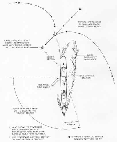
APPROACH AND LANDING
The final approach to the ship should be planned and made smoothly to bring the
drone to a heading into the relative wind at a point off the quarter. Factors to
be taken into consideration in planning the approach are relative wind direction
and velocity, drone gross weight, turbulence, and ship motion.
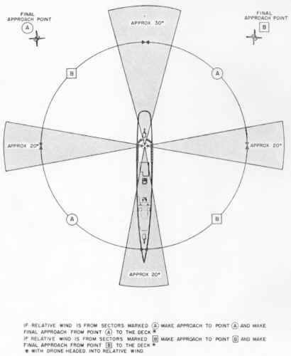
A typical approach is shown in figure 6. Figure 7 may be used as a guide in
determining whether the landing should be made from the port or the starboard
point, based on relative wind direction.
With the drone headed into the relative wind approximately 100 feet away from
the deck, adjust airspeed as required to maintain drone position relative to the
ship and turn the CRUISE-MANUV switch to MANUV.
LANDING
Use the maneuver
stick and altitude knob to bring the drone over the deck at approximately 10 to
15 feet above the deck level. Drone heading may be adjusted as desired by
twisting the maneuver stick. Control drone descent by means of the ALTITUDE
knob.
When the skids touch the deck, set the ALTITUDE readout at "10%"
collective. Stop the engine as described below. Secure the drone to the deck
with the tie down device or tiedowns on the landing gear.
The
final descent should be made as smoothly and gradually as possible and touchdown
should be made with the least possible shock.
|
|
|
Figure 6; Typical Approach
|
Figure 7; Relative Wind Pattern
|
STOPPING
ENGINE
When the drone rests solidly on the deck, run the engine at flight idle for 60
seconds (deck motion permitting), then initiate the engine shutdown sequence by
moving the ENG OFF switch in the direction indicated by the arrow. Leave the
switch in this position until the rotors have stopped turning. The following
actions will occur in the order listed.
1.
Pitch and roll commands are removed by actuation of the carrier loss
relay and the gyro signals are removed, causing the cyclic controls to be driven
to neutral.
2.
The control lock solenoid is actuated and the cyclic controls are locked
at neutral.
3.
The fuel valve solenoid is actuated to shut off the fuel.
If
the control locks do not engage fully, the fuel will not be shut off. In this
event, move the ENG OFF switch in the direction opposite
the arrow, manipulate the maneuver stick slightly in pitch and roll, then move
the ENG OFF switch again in the direction indicated by the arrow.
If
the control locks do not engage, do not leave the ENG OFF switch positioned in
the direction indicated by the arrow for more than 5 seconds. Failure to observe
this caution can result in damage to the control lock solenoid.
TRANSFER
AND LANDING IN LOW VISIBILITY CONDITIONS
Under conditions of low visibility or extensive sea return on the radar,
the CIC controller may lose radar contact with the drone before the deck
controller has acquired visual contact. Under such conditions, a dead reckoning
plot of drone position must be maintained until the deck controller has
acquired visual contact with the drone. A normal transfer of command from CIC to
deck should be accomplished before the drone disappears from radar so that, when
the deck controller sights the drone, an immediate landing can be made. The CIC
controller must, via interphone instructions to the deck controller, direct the
drone flight until the drone is in sight of the deck controller.
Either
of two methods for acquiring visual contact may be employed as follows:
Method
1. Before the drone disappears from radar, plot a course which will carry
the drone, at 50 knots true airspeed, across the path of the ship, slightly
astern. Set altitude command at 300 feet. The deck controller should watch and
listen for the drone. If it passes the ship without being seen, wait until it
reappears on the other side of the radar scope; then plot a new course and make
another pass, this time at less than 40 knots true airspeed. When the deck
controller makes visual contact, a normal landing can be made.
Do
not make passes at less than 300 feet of commanded altitude unless it can be
determined positively that the drone is aft of the ship.
Method
2. Before the drone disappears from radar, plot a collision course and
compute the time of intercept. Set altitude command at 800 feet. When the drone
comes into audible range of the deck controller, place the drone on the same
heading and relative speed as the ship. If the drone still is not visible, the
deck controller must fix the relative position of the drone by its sound.
Maintaining an aural fix on the drone, the deck controller can position the
drone aft of the ship. When it is definitely deter- mined that the drone is
clear of the ship and can be landed safely, the deck controller can reduce
altitude slowly until the drone is visible, then effect a normal landing.
TRANSFER,
SHIP TO SHIP OR SHORE TO SHIP
TRANSFER AT SEA LEVEL
The
following procedures apply to transfer of control of the drone from one station
to another in which the launching station is not higher than 100 feet above the
elevation. of the landing station. If the launching station is more than 100
feet above the landing station, special prelaunch procedures, peculiar to the
exact site, must be followed. (Refer to the paragraph headed TRANSFER, ALTITUDE
TO SEA LEVEL.) If the landing station is at a higher elevation than the
launching station (within the normal altitude command range of the system), no
special prelaunch procedures need be observed.
The
following instructions include two sets of transfer procedures as follows:
1.
When the two stations are within visual range of each other.
2.
When the two stations are out of sight of each other and radar plus dead
reckoning techniques must be used.
In
all transfers, voice communication by radio must be maintained.
During
the transfer procedures set forth below, it is essential that both stations
radiate at the same radio frequency and on the pro- per address setting. This
synchronization of frequency and address selection between two stations in close
proximity should be used only during deliberate transfers.
In
the following instructions, the drone controller at the station from which the
drone is to be launched is referred to as the "sending controller" and
the drone controller at the station at which the drone is to be landed is
referred to as the "receiving controller."
The
procedures are set forth below:
1.
Transfer Within Visual Range
Transfers
within visual range can be accomplished by the deck
controllers without the need for tracking the drone on radar and transferring to
CIC.
A. SENDING CONTROLLER:
(1) Set the switches and controls on the control
monitor as follows:
(a) MASTER switch- -OFF.
(b) TRANSFER switch--DRONE.
(c) AUTO-PURGE-MANUAL switch--MANUAL.
(d) GYRO switch--OUT.
(e) DRONE
ANGLE REL TO SHIP pointer- -aligned with drone (pointer indicates engine air
inlet).
(f) ELAPSED TIME INDICATOR--60.
(2)
Set the switches on the transmitter control as follows:
(a) HV switch--OFF.
(b) CODER switch--EXTERNAL.
(c) KEYED CARRIER - CONSTANT CARRIER switch--CONSTANT CARRIER.
(d) ANT. SEL switch--as directed.
(e) XMTR I - XMTR 2 switch--as directed.
(f) PWR switch--ON. (Wait one minute, minimum.)
(g) HV switch--ON.
(3)
Set the switches and controls on the deck control as follows:
(a) CRUISE-MANUV switch--CRUISE.
(b) MEMORY-STATION switch--STATION.
(c) WEAPONS JETTISON switch--off.
(d) SPARES ON switches--off.
(e) ENG OFF switch--on.
(f) CABLE REL switch--off.
(g) ADDRESS knob--at drone address.
(h) PWR ON switch--on.
(i) ALTITUDE knob--at 000 readout.
(j) AIRSPEED knob--at 00 FWD readout.
(k) HEADING pointer--aligned with drone.
B.
RECEIVING CONTROLLER:
(1)
Set the switches on the transmitter control as follows:
(a) HV switch--OFF.
(b) CODER switch--EXTERNAL.
(c) KEYED CARRIER - CONSTANT CARRIER switch--CONSTANT CARRIER.
(d) ANT. SEL switch--as directed.
(e) XMTR I - XMTR 2 switch--as directed.
(f) PWR switch--ON.
Make
certain that the receiving station HV switch remains at OFF until the actual
station-to-station transfer is to be made. The transfer is effected through this
switch. Simultaneous transmission from both stations will induce loss of carrier
or will cause spurious commands to be received by the drone.
(2)
Set the switches and controls on the deck control as follows:
(a) CRUISE-MANUV switch--CRUISE.
(b) MEMORY-STATION switch--MEMORY.
(c) WEAPONS JETTISON switch--off.
(d) SPARES ON switches--off.
(e) ENG OFF switch--on.
(f) CABLE REL switch--off.
(g) ADDRESS knob--at drone address.
(h) PWR ON switch--on.
(i) ALTITUDE knob--at 500 readout.
(j) AIRSPEED knob--as required to produce 50 knots forward true
airspeed.
(k) HEADING pointer--aligned with intended flight path.
C. SENDING CONTROLLER:
(1)
Perform all the prelaunch operations as in a normal mission.
(2)
Launch the drone, switch to the cruise mode, and climb out to 500 feet
commanded, on a bearing toward the receiving station.
(3)
Approaching the point of transfer, maintain altitude at 500 feet commanded and
set airspeed command as required to produce 50 knots forward true airspeed. Make
certain that the receiving station altitude, airspeed, and heading commands are
synchronized with the sending station. Turn MEMORY-STATION switch to MEMORY,
then turn the HV switch to OFF.
D.
RECEIVING CONTROLLER:
(1)
Turn the HV switch to ON.
(2)
Turn MEMORY-STATION switch to STATION.
(3)
Follow normal mission procedures to effect the approach and landing at the
receiving station.
The
sending controller must stand by his station until the landing at the receiving
station is completed. In the event of malfunction during the transfer operation,
the switching procedure can be reversed and the sending controller can regain
control of the drone.
2.
Transfer, Out Of Sight
Transfers from one
station to another beyond visual range require continuous radar surveillance and
continuous dead reckoning plots, by both stations, of the position of the drone.
The switching operations required to accomplish the actual transfer of control
are the same as those for a transfer within visual range. CIC control, as in a
normal drone mission, may be employed at the discretion of the operating
activity.
The maximum distance
between any two given transfer stations is determined by three factors as
follows:
a.
The range of continuous radar return capability at the one station plus
the range of continuous radar return capability at the other station.
b.
The maximum range of data link control, by the two stations combined, at
the planned mission altitude.
c. Drone range as a function
of ambient atmospheric conditions, weight, and fuel load at launch.
To
accomplish the transfer, proceed as follows:
a. SENDING CONTROLLER:
(1)
Set all switches and controls as in a transfer within visual range.
b.
RECEIVING CONTROLLER:
(1)
Set all switches and controls as in a transfer within visual range.
c.
SENDING CONTROLLER:
(1)
Perform all the prelaunch operations as in a normal mission.
(2)
Launch the drone, switch to the cruise mode, and climb out to 500 feet
commanded, on a bearing toward the receiving station.
(3)
When the receiving station has made tentative identification of the drone on
radar, command an azimuth pattern to confirm identification. Maintain altitude
at 500 feet commanded and set airspeed command as required to produce 50 knots
forward true airspeed. Make certain that the receiving station altitude,
airspeed, and heading commands are synchronized with the sending station.
(4)
Turn MEMORY-STATION switch to MEMORY, then turn the HV switch to OFF. Maintain
surveillance by radar.
d.
RECEIVING CONTROLLER
(1)
Turn the HV switch to ON,
(2)
Turn MEMORY-STATION switch to STATION
(3)
Command an azimuth identification pattern to confirm that control has been
acquired.
(4)
Fly the drone toward the receiving station and follow normal mission procedures
to effect the approach and landing.
TRANSFER,
ALTITUDE TO SEA LEVEL
In making a shore to ship transfer in which the sending station (shore based
site) is more than 100 feet, but not more than 900 feet above sea level, the
barometric altitude control must be synchronized (zeroed) at an artificially
induced static pressure prior to launch. (Refer to the paragraph headed ALTITUDE
COMMAND RANGE in "Operating
Limitations" section.) This operation requires the use of the Altitude
Controller Test Set VPT-10G. The procedure is described below.
It
is essential that the procedure be followed immediately before the transfer is
to take place to minimize the effect of ambient pressure changes following the
synchronization. If it becomes necessary to stop the engine or to turn the
TRANSFER switch on the control monitor to AUX, the synchronizing procedure
described below must be repeated.
Transfer
to sea level from elevation greater than 750 feet must be accomplished without
weapons.
To synchronize the barometric altitude control and accomplish the transfer,
proceed as follows
1.
Set all switches and controls as in a ship to ship transfer.
2.
Position the test set near the right-hand landing gear skid and connect it to a
suitable source of electrical power. Open the STATIC EQUALIZER valve fully. Set
the static altitude controller at approximately the station elevation. Turn the
test set on and allow it to warm up for 15 minutes, minimum.
3.
Exercise the test set altimeter as follows:
a.
Close the STATIC EQUALIZER valve.
b.
Using the altitude controller knob, cycle the altimeter from - 1000 to + 10, 000
feet 2 or 3 times. Leave it set at +10,000 feet.
4. Leak test the
test set as follows:
a.
Hold the STATIC LEAK TEST button depressed lightly but firmly.
b.
Observe the altimeter for any decrease in indicated altitude. If the leak rate
is greater than 100 feet per minute, determine the cause and correct it.
c.
Release the STATIC LEAK TEST button.
d.
Set the altitude controller at the station elevation. e. Open the STATIC
EQUALIZER valve.
5. Disconnect the
drone static line at the barometric altitude control static port. Connect the
altitude controller test set hose to the barometric altitude control static port
and connect the quick release coupling to the tester. Close the STATIC EQUALIZER
valve.
6.
Leak test the system as follows:
a. Using the altitude controller knob, set the altimeter
reading at +10,000 feet.
b. Hold the STATIC LEAK TEST button depressed lightly but firmly.
c. Observe the altimeter for any decrease in indicated altitude. If
the leak rate is greater than 200 feet per minute, determine the cause and
correct it.
d. Release the STATIC LEAK TEST button.
e. Set the altitude controller at the station elevation.
f. Open the STATIC EQUALIZER valve.
7.
Set the pointer on the test set altimeter to station elevation plus or minus the
altimeter correction on the calibration card. Close the STATIC EQUALIZER valve.
8.
Start the drone engine using normal procedures.
Do
not turn the TRANSFER switch on the control monitor to DRONE; leave it at AUX.
The
technician must remain crouched as low as possible while under the rotors.
9.
Using the altitude controller, set the test set altimeter as follows:
|
|
If station elevation
(in feet) is:
|
|
Set Altimeter to:
|
|
|
|
100-750
750-850
850-900 |
|
0*
100*
140* |
|
|
| * Plus or minus correction on
calibration card. |
Make
certain that step 9 is performed with the control monitor TRANSFER switch at
AUX.
10.
Make certain that the ALT SYNC meter pointer is in the green area, then turn the
TRANSFER switch to DRONE.
Make
certain that the TRANSFER switch remains in the DRONE position as long as the
umbilical cables remain connected. If the switch is turned to AUX, even
momentarily, the altitude reference applied in step 9 will be removed.
11.
Return the test set altitude controller to station elevation. Open the STATIC
EQUALIZER valve. Turn the test set off and remove and stow the test set hose.
12.
Reconnect the drone static line to the barometric altitude control. Make certain
that the line is tight, but do not over tighten the fitting.
13.
Clear the launching area. Make certain that the prelaunch tie down device is
secure.
Do
not displace the ALTITUDE RATE switch until ready to launch the drone. Upward
movement of this switch releases the tie down device
14.
Readjust the ALTITUDE knob as required until the COLLECTIVE FOLLOW UP POSITION
meter indicates 10. The ALTITUDE readout indication should be as follows:
|
If station elevation (in feet) is:
|
Altimeter setting in step 9 is:
|
Altitude readout at 10% FU should be:
|
|
|
100-750
750-850
850-900
|
0 (corrected)
100 (corrected)
140 (corrected)
|
Station elevation - 0 to +100
Station elevation -100 to +0
Station elevation -140 to -40
|
|
15.
If the altitude readout indication obtained in step 14 is
not proper, stop the engine using ENG OFF switch on the deck control
(C-3314/SRW-4C). Repeat steps 5 through 14.
DO
NOT use the STOP switch on the control monitor after TRANSFER switch has been
turned to DRONE!
16.
If the altitude readout indication obtained in step 14 is proper, perform the
prelaunch command tests, in both cruise and maneuver modes, in accordance with
steps 1 through 20 of figure 3, except that in step 14 of figure 3, the altitude
commanded should be that noted in step 14 above plus 50 feet, to obtain a
follow-up reading of 20 ± 10%.
17.
On completion of the prelaunch command tests, turn the CRUISE-MANUV switch to
MANUV, turn the GYRO switch to IN, and release the umbilical cables and tiedown
device.
18.
Using the ALTITUDE knob, increase altitude and hover the drone approximately 20
feet over the launching spot for approximately one minute.
19.
Head the drone in the direction of the receiving station and effect the transfer
as in a normal sea level transfer.
At
the point of transfer, both the sending and receiving stations must have the
drone in visual or continuous radar contact.
After the drone has landed at the receiving station and the engine stopped, it
is not necessary to remove the artificial reference
from the barometric altitude control. The next time power is applied through the
umbilical cable, the control automatically resynchronizes to its existing
station elevation.
SHUTTING
DOWN
To turn off the shipboard components,
proceed as follows:
1. Turn control monitor MASTER switch to
OFF.
2. Turn CIC control and
deck control PWR switches off.
3. Turn CIC transmitter
control and deck transmitter control PWR and HV switches off.
End of Normal Procedures Section

|