Description

DRONE AND SHIPBOARD GUIDANCE SYSTEM

The Navy Model QH-50D Drone (hereinafter referred to as the drone) is a remotely controlled, rotary- wing, weapon-carrying vehicle designed specifically for 
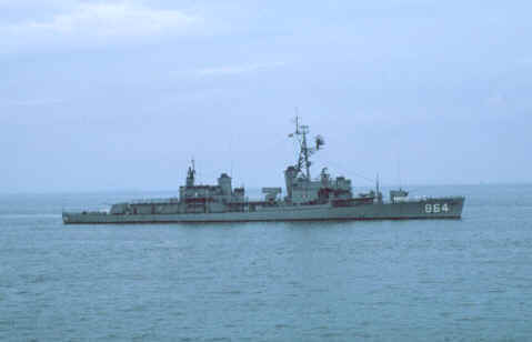
deployment from the deck of destroyer type ships in antisubmarine warfare (See figures 1 and 2).

The Target Control System AN/SRW-4B (hereinafter referred to as the shipboard guidance system) is used to control the drone in the accomplishment of its mission.

The drone and the shipboard guidance system, together, constitute the DASH (Drone Anti-Submarine Helicopter) Weapon System which is a basic feature of the Navy FRAM (Fleet Rehabilitation And Modernization) program.

The drone and certain components of the over-all system are manufactured by, or under the program management of, Gyrodyne Helicopter Company. The model T50- BO- 10 or T50-BO- 12 Turboshaft Engine (hereinafter referred to as the engine) and the remainder of the system components are items of government furnished equipment (GFE). Figure 3 of this section lists the principal components of the DASH Weapon System and figure 4 lists the leading particulars of the drone.

The drone is maintained stable in flight by the Automatic Flight Control Set AN/ASW-20 (AFC set). The Radio Receiving Set AN/ARW-78 (receiving set) receives and decodes the command signals which originate on the destroyer and superimposes them on the stabilization system. Primary electrical power for the airborne system is obtained from the airborne generator which is driven by gearing from the rotor drive system.

The digital command guidance, or data link, system is of the pcm/fm (pulse code modulation of a frequency modulated subcarrier) type, in which the commands are transmitted to the drone as discrete binary coded pulses.

The drone is capable of carrying either one of the two following weapon stores:

1. Two Mark 44 Mod 0 torpedoes. 
2.
One Mark 46 Mod 0 torpedo.

The drone mission capabilities are described in "Operating Limitations” section under the paragraph headed OPERATING ENVELOPE. 


Figure 2; QH-50D Drone General Arrangement

1. Tip Brakes
7. Airborne Generator
13. Antenna
2. Upper rotor assembly
8. Transmission housing
14. MK-44 Homing Torpedo
3. Static pressure pick-up
9. Fuselage frame and    
    transmission support housing
15. T50 series Turbine Engine
4. Rotating controls
10. AFC set components
16. Servo actuator
5. Lower rotor assembly
11. Fuel Tank
17. Non-rotating controls
6. Bell Housing
12. Landing Gear


Principal System Components: 

Airborne Components   Figure 3

Item

Common Name

Nomenclature

1
Airframe
Airframe System
2
Engine*
Model T50-BO-10 or T50-BO-12 Turboshaft Engine
3
Antenna
Antenna AS-1886/AKT-20
4
Receiver
Radio Receiver R-1164/ARW-78
5
Decoder
Command Signals Decoder KY-476/ARW-78
6
Airborne generator
Alternating Current Generator G-59/U or G-59A/U
7
Barometric altitude control
Automatic Pilot Altitude Control C-4748/ASW-20 or Barometric Altitude Control Assembly, Y70E620149-001
8
Roll and pitch (vertical) gyroscope
Roll and Pitch Displacement Gyroscope CN-1084/ASW-20 or CN-785/ASW-20
9
Directional gyroscope
Directional Displacement Gyroscope CN-786/ASW-20
10
Gyroscope control box
Gyroscope Control C-3817/ASW-20
11
Control amplifier
Electronic Control Amplifier AM-3082A/ASW-20 or AM-3082/ASW-20**
12
Servo actuator
Electro-Mechanical Rotary Actuator TG- 95/ASW- 20
13
Relay assembly
Relay Assembly RE-862/ASW-20


NOTE

Items 4 and 5 comprise the Radio Receiving Set AN/ARW-78 (receiving set)

Items 6 through 13 comprise the Automatic Flight Control Set AN/ASW-20 (AFC set)

* Government furnished equipment (GFE).
** With Avionics Change No. 362 incorporated.


Principal System Components: 

Shipboard Components   Figure 3-continued

Item

Common Name

Nomenclature

14
Deck Control*
Transmitter Control C-3314/SRW-4C
15
Deck control pedestal*
Transmitter Control Pedestal MT-2351/SRW-4C
16
CIC control*
 Transmitter Control C-3313/SRW-4C
17
Coder (2)*
Audio Frequency Coder KY-342/SRW-4C
18
Transmitter control (deck)*
Transmitter Control C-2801/SRW-4
19
Transmitter control (CIC)*
Transmitter Control C-2804/SRW-4
20
Transmitter (2)*
Radio Transmitting Set AN/URW-14A
21
Interconnecting box (2)*
Interconnecting Box J- 1318/SRW-4
22
Interconnecting box*
Interconnecting Box J-1039/SRW-4
23
Interconnecting box*
Interconnecting Box J-1052/SRW-4
24
Power supply*
Power Supply PP-2288/SRW-4
25
Relay assembly*
Relay Assembly RE-434/SRW-4
26
RF transmission line switch*
Radio Frequency Transmission Line Switch SA-631/SRW-4
27
Antenna (2)*
Antenna AT-948/U


NOTE

Items 14 through 27 comprise the Target Control System 
AN/SRW-4B (shipboard guidance system)

* Government furnished equipment (GFE).


Principal System Components: 

Auxiliary Operating Equipment     Figure 3-continued

Item

Common Name

Nomenclature

28
Control monitor
Control Monitor C-4298/ASW-20
29
Motor-generator
Motor-Generator PU-559/U or PU-610/U
30
Auxiliary relay box
Shipboard Auxiliary Relay Box Y63-315620-36 or Relay Assembly RE-832/ASW-20 
31
Launcher-retriever system
Launcher-Retriever System
32
Weapon skid*
Aero 22A Skid
33
Tie down device
Prelaunch Tiedown Device Y63SB80029-001


* Government furnished equipment (GFE).


Figure 4; Leading Particulars of the QH-50D DASH Drone

General

  Rotor disk diameter 
20 ft 0 in.
  Length, rotors fore and aft
20 ft 0 in
  Width, maximum, rotors fore and aft
5 ft 3 in.
  Landing gear skid length
5 ft 3.64 in.
  Landing gear skid tread, center-to-center
5 ft 0 in.
  Height, over-all static
9 ft 8.5 in.
  Rotor ground clearance (static)
6 ft 0 in.
  Minimum clearance under lower rotor
3 ft 8.7 in.
  Weight, empty
1087 lb
  Weight, normal gross*
2340 lb

* Weight based on wooden blades and two Mark 44 Mod 0 Torpedoes with Mark 24 Mod 2 Air Stabilizers installed. For other configurations, adjust weights shown above as follows:
  Fiberglass Blades
Deduct 52 lb
  One Mark 46 Mod 0 Torpedo with Mark 31 Mod 0 Air Stabilizer
Deduct 288 lb
  Operational Telemetry package installed, equivalent ballast removed
 No change


ROTORS (2 semi rigid)

 
2
  Airfoil section at root (theoretical)
NACA 0017 Airfoil section at tip (theoretical) 
 
NACA 0012 Chord at root (theoretical)
  Chord at root (theoretical)
6. 5 in.
  Area per blade (actual)
6. 75 sq ft
  Twist
0. 1 deg per in. (stations 30 to 120)
  Taper ratio
2:1
 
314.2 sq ft
  Solidity ratio (effective)
0.0862
  Disk loading (at 2340 lb normal gross weight)  {Weight/Rotor disk area}
7.45 psf
  Rotor speed
610 rpm, nominal


Engine

  Make
Boeing
  Model
T50-BO-10 or T50-BO-12
  Type
Two-shaft gas turbine, two combustion chambers, independent output turbine
Shaft Horsepower
  Interstage bleed valve active
330 at 90ºF, military rated 365 at 59ºF, military rated
  Interstage bleed valve inactive
300 at 90ºF, nominal available 330 at 59ºF, nominal available
  Output shaft speed
6000 rpm, nominal
  Fuel
MIL-T-5624 grade JP-5
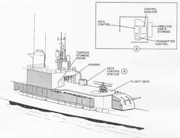
 

DASH WEAPON SYSTEM MISSION

    The drone is controlled from either one of two stations on the destroyer: one at the flight deck (figure 5), the other at the combat information center (CIC). The drone is housed in a hangar on the destroyer and is transported along the deck on the launcher-retriever restraint cables. Shipboard radar is used for tracking the drone, and sonar is used for the detection of underwater targets. A display system combines the radar and sonar information to enable the CIC controller to position the drone with respect to the target. A typical combat mission against an enemy submarine is described briefly in the following steps.

1. The fueled and armed drone is moved from the hangar and spotted at the launch area on the flight deck.
2. The drone is secured to the deck by means of a tiedown device incorporating a remotely actuated disconnect coupling, and the restraint cables are removed.
3. Using the control monitor, the deck controller starts the drone engine, and the rotors are brought to normal rpm by the engine limiter. The controller transfers power from the auxiliary power source to the drone generator, performs a brief prelaunch check, and actuates the umbilical cable remote disconnect.
4. The deck controller actuates the hold-down release, applies an altitude command, and maneuvers the drone away from the ship. He executes a smooth climb-out and vectors the drone in the direction of the target.
5. The deck controller transmits to the CIC controller, via interphone, the altitude, airspeed, and heading of the drone. The CIC controller sets this data into the CIC control. When the drone appears on the CIC radar display, an integrated transfer of control from deck to CIC Is effected.
6. The CIC controller plots the drone course, taking into account relative motion of destroyer and target, wind direction, and drone heading and speed. The CIC controller heads the drone on this course and monitors the closure on target, readjusting drone heading, ff necessary, to compensate for unpredicted changes.
7. As the drone approaches the target area, the CIC controller establishes the proper drone altitude, airspeed, and heading for weapon delivery. At the optimum torpedo drop point, the CIC controller releases the weapon or weapons. The CIC controller then commands the proper altitude and heading for the return to the vicinity of the ship.
8. When the drone comes into sight, control is transferred from the CIC controller to the deck controller who executes the approach and landing.
9. The deck controller stops the engine by remote control, the restraint cables are rigged, and the drone is returned to the hangar. 

DRONE

The drone (figures 1 and 2) is a helicopter of the coaxial rotor type. The two-bladed semi-rigid rotors rotate about a common center; the upper rotor turns counterclockwise, and the lower rotor turns clock- wise (viewed from above). Power is transferred from the turbo-shaft engine to the rotors through a two-stage transmission system. Engine speed is maintained within limits by a power turbine limiter and a fuel control unit.

The drone structure is of open construction and consists essentially of a transmission and fuselage support casting, tubular landing gear struts and skids, and the tubular aft fuselage assembly. The fuel tank and certain components of the AFC set are mounted on the aft fuselage. 


SHIPBOARD GUIDANCE SYSTEM

The shipboard guidance system provides means for controlling the drone from the destroyer. All components of this system (figure 3) are installed on shipboard.

The shipboard guidance system consists of certain basic components common to many target control systems, plus other components for specific use with the DASH Weapon System. These specific components are items 14 through 17 of figure 3. Items 18 through 27 of figure 3 may be used in other drone or target control systems. 


ENGINE

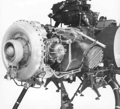
    The drone is powered by a Boeing Model T50-BO- 10 or - 12 two- shaft gas turbine engine, which consists of two major sections; a gas producer section, and a power output section. There is no mechanical connection between the rotor in the gas producer section and the rotor in the power output section. Their rotational speeds may very independently as required by the load.

The gas producer section consists of a two-stage axial and centrifugal compressor directly coupled to a single-stage axial flow turbine wheel, two combustion chambers, an accessory drive section, and a rotor housing and sump.

The power output section comprises an axial flow, single-stage turbine wheel, power output reduction gearing, accessory drive gearing, and an output shaft.

An interstage bleed valve is mounted on the underside of the bleed air collector, and is used to provide a means of discharging a portion of compressor air to atmosphere to prevent compressor surge during engine operation. The bleed valve is opened by a bellows and linkage assembly when the differential between interstage pressure and compressor pressure exceeds a preset value. The interstage bleed valve is installed on both T50-BO- 10 and - 12 engines; however, on some T50-BO-10 engines, due to variations in compressor internal configuration, the bleed valve is inactive. T50-BO-10 engines with activated bleed valves are easily identified by the presence of a pneumatic tube (compressor discharge pressure line) connecting the bleed valve to the compressor case. These engines are military rated at 330 shp at 90º F. T50-BO-10 engines with inactive bleed valves do not have the pneumatic tube installed, and have a nominal available horsepower rating of 300 shp at 90º F. All T50-BO-12 engines utilize activated bleed valves, and are military rated at 330 shp at 90ºF, and 365 shp at 59ºF.

The nameplate mounted on the accessories section housing of the T50- BO-10 or -12 engines shows the horsepower rating of the engine under standard ambient conditions (59ºF). The horsepower rating shown on the nameplate of T50-BO-10 engines with inactive interstage bleed valves is 330 shp. This rating is equivalent to a minimum rating of 300 shp at 90º F. T50- BO- 10 engines with activated interstage bleed valves have a horsepower rating of 365 shp shown on the nameplate. This rating is equivalent to a minimum rating of 330 shp at 90º F. Since all T50-BO-12 engines have activated interstage bleed valves, the horsepower rating shown on the nameplate of these engines is 365 shp (equivalent to a minimum rating of 330 shp at 90ºF).

ENGINE IGNITION SYSTEM


The engine ignition system consists of a relay, an ignition unit, two igniter plugs (one for each burner), and the necessary cabling.

The ignition relay provides means for energizing the ignition unit and igniter plugs. It is used only during the starting cycle.

The 28-vdc input, capacitor-discharge ignition unit provides a high voltage output for the igniter plugs during the starting cycle.

Each igniter plug has two electrodes, and is connected to the ignition unit. During the starting cycle, high voltage from the ignition unit is applied to the center electrode, which sparks to the ground electrode, igniting the fuel. After combustion occurs, the igniter plugs are de-energized; combustion is self-sustaining.

STARTER-GENERATOR

An air-cooled starter-generator is in constant engagement with the gas producer accessory drive gear train. During the starting cycle, the starter-generator is energized to drive the gas producer rotor until combustion has occurred. Generator output is not used in the present system.

ENGINE INSTRUMENTS

All engine-monitoring instruments are located in the control monitor. These instruments are disconnected from the engine when the umbilical cables are disconnected. The functions of the instruments are discussed under OPERATING CONTROLS AND INDICATORS. Instrument markings are discussed in Section V.

ENGINE FUEL SYSTEM

The engine fuel system includes a low-pressure filter, a fuel pump, a fuel control unit, a power turbine limiter, a fuel shutoff valve, a flow divider, two fuel nozzles, and interconnecting fuel and air lines.

The fuel control unit is modulated by the power turbine limiter, and in turn controls gas producer rotation to maintain the power output section at constant speed as required by engine loading. The power turbine limiter and the fuel control unit are inter- connected by a flexible air line.

The electrically operated fuel shutoff valve is used to shut the engine down safely from any operating condition. The valve is opened and closed electrically, but does not require any current to hold it in either position.

The flow divider is used to distribute fuel flow between the primary and secondary nozzle orifices in each burner assembly. Internal passages to the primary orifices are always open. When the fuel nozzle pressure reaches 150 psig, a valve in the flow divider opens, providing fuel flow through the secondary orifices. Engine fuel is MIL-T-5624, grade JP-5. The capacity of the fuel tank is 52 gallons (353.6 pounds).

ENGINE OIL SYSTEM

    The engine incorporates all lubrication system components necessary for engine operation under the climatic, altitude, and attitude conditions that fall within the engine operating envelope. The lubrication system consists of a supply sump, a lube and scavenge pump and pressure regulator valve, a filter bypass valve, an oil cooler and thermal and pressure relief valve, a magnetic chip detector, a torque sensing system, and interconnecting lines and passages. Lubricating oil in accordance with Specification MIL- L-23699 is used in the engine.

    Oil is drawn from the sump by the pressure element of the lube and scavenge pump, which pressurizes the system and supplies lubrication to the entire engine. The other two elements of the pump scavenge the rotor housing and output section. Drainage oil from other gas producer locations returns to the sump by gravity. System oil pressure is maintained by the internal relief valve. A full-flow type filter and filter bypass valve arrangement, which includes a disposable cartridge, is utilized in the engine. The bypass valve opens to assure adequate oil flow to the engine bearings when filter pressure drop exceeds 25 psi. A screen is located in the suction passage to each oil pump element. The oil cooler is mounted on the bottom side of the engine, and utilizes exhaust eductor air for cooling. Oil having temperatures below 71ºC (160ºF) bypasses the oil cooler by means of a thermostatically operated valve. The cooler also includes a bypass valve which opens when the pressure drop across the cooler exceeds 20 psi.


ROTOR SYSTEM

ROTOR ASSEMBLIES

    Rotary motion is imparted to each rotor by means of a saddle splined to each of the rotor shafts. The design and construction of the upper and lower rotor saddles and associated parts is similar but not identical. Axial motion of the saddles is prevented by spacers and a nut on the top of each rotor shaft. Pivotally mounted on each saddle are two plates which support the rotor spindles and tip brake bellcrank shafts. Pivotally mounted on the rotor spindles are the blade hub and pitch horn fittings which contain a series of radial and thrust bearings.  

    These fittings are secured axially on the spindles by positively locked retaining screws. Lugs are pro- vided on the outboard ends of the hubs to receive the rotor blades, which are provided with metal reinforcing plates at the root. A tip brake is pivotally mounted in the tip of each blade. The tip brake is connected to a crank arm on the tip brake shaft by a control rod, which runs through a tube bedded within the blade. The tip brake is opened by an inward pull on the control rod and is normally held closed during flight by centrifugal force acting on a counterweight on the brake. The control rod is connected to the tip brake through pin and slot connection to permit free outward motion of the control rod. The upper and lower rotor tip brake mechanisms are connected in such a manner that they move in relatively opposite directions. This permits either the upper or lower rotor tip brakes to be ex- tended at will without affecting the other.

Gust locks are provided for each rotor to prevent flapping or teetering while the rotors are static or rotating at low or medium speed during acceleration and deceleration. These locks are spring-urged into engagement and are disengaged by centrifugal force when approximately 75 percent of the full 610-rpm rotor speed is reached (approximately 460 rpm).

ROTATING CONTROLS

    Collective pitch and cyclic pitch control movements are applied to the rotor blades through swash plate assemblies on the rotor mast below each rotor (See figure 6 ). The design and construction of the two assemblies is similar but not identical, though they serve the same function. Each swash plate assembly consists primarily of an inner and outer ring with two single- row ball bearings between the rings. Each swash plate assembly is supported by a two-axis gimbal ring so that its plane of continuous rotation can be deflected longitudinally and laterally. The gimbal ring for the lower swash plate assembly is pivoted on a support, which is adapted for axial, but not rotative, movement on a cylindrical extension of the transmission bell housing. Axial motion is imparted by a collective pitch yoke which also restrains the inner swash plate ring against rotation (See figure 7). The inner swash plate ring is provided with two forked extensions: one aft of center, and one abeam to the left. Each fork is connected to an independent series of links and levers, which control the deflection of the plane of rotation of the outer swash plate ring through the non-rotating inner ring. Rotation is imparted to the outer swash plate ring, at the same rate as the rotor, by scissors linkages secured to an adapter, which is keyed to the rotor saddle.

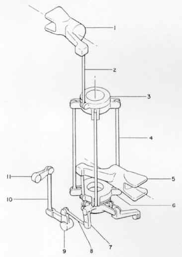
Figure 6; Rotating Controls

1.  Central hoisting fitting

2.  Air deflector

3.  Upper rotor tip brake bellcrank and link assembly

4.  Upper pitch link assembly

5.  Tip brake swivel housing assembly 

6.  Upper swash plate assembly 

7.  Lower tip brake horn

8.  Lower rotor tip brake bellcrank and link assembly

9.  Lower pitch link assembly

10.  Lower swash plate assembly 

11.  Lower rotor hub assembly

12.  Lower gust lock and scissors assembly 

13.  Swash plate control link assembly

14.  Upper gust lock and scissors assembly 

15.  Upper rotor hub assembly

16.  Lower tip brake swivel actuator strut


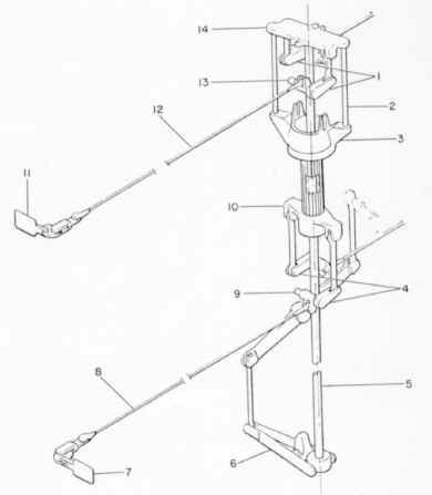
Figure 7; Collective Pitch System

1.  Upper blade hub and pitch horn assembly

2.  Upper pitch link assembly

3.  Lower blade hub and pitch horn assembly

4.  Lower pitch link assembly

5.  Collective yoke

6.  Servo actuator output arm

7.  Short servo link

8.  Walking beam assembly

9.  Link assembly

10. Lower swash plate assembly

11. Swash plate control link assembly

12. Upper swash plate assembly

    The upper swash plate assembly is gimbal-mounted on a support, which slides on, and rotates with, a sleeve, which is splined to the lower rotor shaft. Thus, the relative speed between inner and outer rings is twice the rotor speed. Four control links, 90 degrees apart, link the upper inner swash plate ring to the lower outer swash plate ring so that the same axial and tilting control movement is imparted to both swash plate assemblies simultaneously. A pitch link connects each rotor hub pitch horn to its associated outer swash plate ring. This pitch link leads the blade-feathering axis by 90 degrees.

    Collective pitch, which determines thrust (lift) for given rotor speed, is controlled by moving the swash plate assemblies axially on the rotor mast to cause all the rotor blades to rotate equally about their feathering axes. Tilting the swash plate assemblies causes a cyclic pitch change in each blade as it rotates. (See figures 8 and 9 ). Since the pitch links lead the blades by 90 degrees, the continuously varying pitch of each blade will cause the rotor disks to tilt in correspondence with the tilt of the swash plate assemblies. Thus, tilting the plane of rotation of the swash plate assemblies forward will cause the drone to assume forward speed. Lateral and rear- ward speed can be achieved by tilting the swash plate assemblies in the appropriate direction. Longitudinal and lateral tilt can be combined to cause flight in any direction with no change in heading of the fuselage. 

Figure 8; Longitudinal Cyclic Pitch System

1. Upper swash plate assembly

2. Swash plate control link assembly

3. Lower pitch link assembly

4. Lower swash plate assembly

5. Servo actuator output-arm

6. Short servo link

7. Bellcrank assembly

8. Link assembly

9. Bellcrank assembly

10. Link assembly

11. Lower blade hub and pitch horn assembly

12. Upper pitch link assembly

13. Upper blade hub and pitch horn assembly


Figure 9; Lateral Cyclic Pitch System

1.  Upper blade hub and pitch horn assembly

2.  Upper pitch link assembly

3.  Upper swash plate assembly

4.  Swash plate control link assembly

5.  Lower blade hub and pitch horn assembly

6.  Lower swash plate assembly

7.  Bellcrank assembly

8.  Link assembly

9.  Bellcrank assembly

10. Short servo link

11. Servo actuator output arm


    The swash plates are automatically locked against cyclic pitch displacement during acceleration and deceleration of the rotors to prevent damage to the rotating control system. This cyclic control lock mechanism is mounted on the after side of the servo actuator and consists of two solenoid actuated pawls which engage notches in the longitudinal and lateral cyclic output arms of the servo actuator. The locks are engaged on the application of an engine-off command and are disengaged, after the rotors reach normal rpm, when power is transferred from the auxiliary motor-generator to the airborne generator. The control locks also may be actuated manually.

Fuselage heading is controlled by movable tip brakes at the tips of the rotor blades (See figure 10). At a given steady state heading of the fuselage, torque is applied equally to each rotor through the second stage pinion and upper and lower rotor shaft drive gears. 


Figure 10; Tip Brake System

1.  Upper tip brake bellcrank and link assemblies
2.  Lower tip brake swivel actuator strut
3.  Tip brake swivel assembly
4.  Lower tip brake bellcrank and link assemblies
5.  Tip brake actuator tube
6.  Tip brake yoke
7.  Lower tip brake
8.  Lower tip brake control rod
9.  Lower tip brake shaft
10.  Lower tip brake horn
11.  Upper tip brake
12.  Upper tip brake control rod
13.  Upper tip brake shaft
14.  Upper tip brake horn

Since the applied torques are equal and opposite, the differential torque is zero. When the tip brakes on one of the rotors are extended, the aerodynamic resistance of that rotor is increased, and a torque differential in the transmission is induced. This differential torque produces a change of fuselage heading. When the tip brakes are retracted, the zero torque differential is restored and the fuselage remains oriented at the new heading.

Since the upper rotor turns counterclockwise, and the lower rotor turns clockwise (viewed from above), extension of the upper rotor tip brakes causes the fuselage to alter heading to the right. Extension of the lower tip brakes causes a turn to the left.

    The linkage which controls the tip brakes includes an axial motion shaft running through the hollow center of the upper rotor shaft, a tip brake actuator horn, and links to the upper rotor tip brake bellcranks. Motion is transmitted to the lower tip brake bellcranks by means of struts from the horn to a swivel housing below the upper rotor. The swivel housing provides roller thrust bearing engagement with an axial motion sleeve splined to the lower rotor shaft and through the upper swash plate assembly. The lower tip brake actuator horn is secured to the lower end of the sleeve and is connected by links to the lower rotor tip brake bellcranks.


TRANSMISSION SYSTEM

    Power is applied from the engine to the rotors through the two-stage transmission. A quill shaft transfers power from the output section of the engine to the transmission first stage input pinion which meshes with the first stage gear (See figure 11). The first stage gear is mounted on, and splined to, the hub of the second stage pinion. The two second stage gears are mounted parallel to each other on a common center of rotation. Both mesh with the second stage pinion, one above and one below. Thus, rotation of the second stage pinion in a given direction causes the two-second stage gears to rotate in relatively opposite directions. 

    The upper second stage gear drives the tubular lower rotor shaft clockwise (viewed from above) and the lower second stage gear drives the tubular upper rotor shaft counterclockwise within the hollow center of the lower rotor shaft. Total gear reduction from engine output to rotor shafts is 9.83 to 1. The transmission gears, shafts, and bearings are contained in a housing, which consists of three major sections. The main transmission housing, in the center, contains the first and second stage gearing. The upper conical bell housing section contains the main rotor thrust bearing. This thrust bearing is of the tapered roller type. 


Figure 11; Transmission Gearing, Schematic Diagram

1.  Generator drive gearing

2.  Lower rotor shaft drive gear

3.  Upper rotor shaft drive gear

4.  Tip brake actuator tube

5.  First stage pinion

6.  Quill shaft

7.  First stage gear

8.  Second stage pinion

9.  Servo actuator drive shaft

10. Overrunning clutch

11. Lower rotor shaft

12. Upper rotor shaft


    The lower section constitutes a transmission oil sump and a housing for the displacement type oil pump. Oil is fed at a nominal 60 psig to all gears and bearings in the transmission as well as to the rotor shaft bearings. Scavenging is by gravity feed. Oil used in the transmission is Specification MIL- L-23699. The oil fill cap is on the upper left side of the transmission housing. The transmission oil sight gage is located on the lower left side of the transmission. Sockets are provided in the lower transmission casting to receive the landing gear struts and the aft fuselage members. The bomb shackles also are supported by this casting. Torque is imparted to the upper and lower rotor shafts by the lower and upper second stage gears, respectively, through splines. 

    Upper rotor shaft thrust is transmitted to the lower rotor shaft by two thrust bearings at its upper end. Thus the total rotor thrust is transmitted to the upper section of the transmission housing through the main thrust bearing mentioned above. The splined couplings between the second stage gears and the rotor shafts are capable of limited axial movement, eliminating the transfer of rotor thrust loads to the gear hubs, and consequently to the mesh. 

    The accessory drive gearing is incorporated in the upper transmission housing. This gearing transmits power from the rotor drive system to the airborne generator and the four-axis rotary servo actuator. A bevel gear, keyed to the hub of the lower rotor shaft second stage gear, provides means for power takeoff. Rotor shaft speed is stepped up to 1736 rpm for the input to the servo actuator, and to 8000 rpm for the airborne generator. An overrunning clutch in the accessory drive gearing to the servo actuator permits the application of auxiliary prime mover power to the actuator for test purposes.


DRONE ELECTRICAL POWER SUPPLY SYSTEM

Electrical power for all the airborne electrical circuits is provided by an airborne generator, which is driven, through gearing, by the rotor drive system. The generator provides the following nominal voltages

115 volts, 400 cps, phase A, B, C.

22 volts, 400 cps, phase 1, 2, 3.

26 volts, 400 cps, phase A, phase A-90 degrees.

A three-phase rectifier circuit in the relay assembly, operating from the 22-volt 400 cps supply, provides unfiltered 28-vdc power to operate relays, solenoids, and other equipment. The 22-volt generator winding also supplies power to two three-phase rectifier circuits in the electronic control amplifier, one of which provides an unregulated 28-vdc supply for internal use within the unit.

The second rectifier circuit is used in conjunction with the 28-vdc supply in a voltage doubler circuit to produce a 39-vdc supply for transistor biases.

Power is transmitted to the various units of the system by means of wiring harnesses and cables.

LANDING GEAR

The landing gear consists of four tubular struts and two tubular skids. Fittings at the ends of each skid include provisions for clamping the drone to the deck in the hangar, and for the installation of restraint rollers for deck handling.

An electrical switch is mounted on each skid. These switches are actuated when the drone makes or breaks contact with the deck. When the drone is on the deck, the switches serve to short out follow-up washout circuits in the AFC set. When the drone is airborne, the switches serve to open the engine-off command circuit so that the drone engine cannot be shut off remotely while the drone is airborne. The control lock and under voltage cutout circuits also are interlocked through these switches.


AFC SET AND RECEIVING SET

The components of the AFC set and receiving set are listed in figure 3. The servo actuator is mounted on the forward side of the accessory drive section of the transmission, and receives its mechanical input power from the accessory drive gearing. The airborne generator is mounted on the after side of the generator support housing assembly, and is driven by the accessory drive gearing. The decoder is bracket mounted on the upper tubes of the aft fuselage assembly. The control amplifier, radio receiver, and relay assembly are mounted on the after side of the avionic panel, which is supported by the tubing of the aft fuselage assembly. Mounted on the left side of the transmission lower housing are the directional gyroscope and the gyroscope control box. The roll and pitch gyroscope and the barometric altitude control are mounted on the right side of the transmission lower housing.

The antenna is of the dual type and is attached to an arm pivotally mounted near the after end of the left skid. One portion of the antenna serves to receive the command signals transmitted from the ship and the other portion serves to transmit telemetry data back to the ship. As the drone leaves the deck, the antenna drops to a position below the skid so that it will not be shielded by the tubular landing gear.  The antenna is retracted by contact with the deck.

The avionic components are interconnected through a wiring harness and the relay assembly. The AFC set umbilical cable receptacle, used for a prelaunch check, and three test receptacles, used during maintenance and test operations, are incorporated in the relay assembly. The test receptacles must have their shorting caps installed prior to flight.

The roll and pitch and the directional gyros are mounted in brackets which can be loosened or removed so that the gyros can be displaced in the appropriate axes for test purposes.

There are two external adjustments on the avionic equipment.

1. The directional gyro control is adjusted, prior to launch, according to the hemisphere and latitude of the operating area. The adjustment requires the set- ting of two controls: a N-S hemisphere selector switch, and a latitude control. The hemisphere selector is a slotted shaft which must be turned to N or S as required. The latitude control is a knob with a dial graduated from 0 to 90 (degrees of latitude). The latitude control establishes the proper correction rate for drift resulting from earth rotation. The selector switch establishes the polarity of the correction signal.

2. A slotted shaft on the decoder must be set with the deep end of the slot toward one of the positions A through H, as predetermined by the operating activity. (Corresponding settings are made on the CIC control and the deck control.) This permits the drone to interpret only one of the eight possible coded address structures which can be transmitted, all on the same frequency. This "address selection" permits control of more than one drone from each destroyer; however, other ships or stations radiating on the same frequency, within a given area, can cause carrier loss response or the passage of spurious commands even though different addresses are used. 

SHIPBOARD GUIDANCE SYSTEM EQUIPMENT

The components of the shipboard guidance system are listed in figure 3. All the components are semi-permanently mounted on shipboard. The system is powered by the destroyer 115-volt, 60 cps, single-phase supply. Twenty-eight volts DC for relay operation is derived from Power Supply PP- 2288/SRW-4.

The system includes duplicate transmitters, coders, and antennas for safety.  The alternate transmitter-coder combination or antenna can be switched on at either the deck or CIC control station. Coordination of command between deck and CIC is effected through the destroyer inter- phone system.

The control equipment installed at each station is:

DECK

Combat Information Center (CIC)

Deck control 

CIC control

Deck control pedestal

Transmitter control (CIC)

Transmitter control (deck)

Control monitor


DECK CONTROL AND DECK CONTROL PEDESTAL

The deck control (figures 12 and 13) provides the knobs, indicators, switches, and maneuver stick required by the deck controller to command the drone. This unit is mounted on the deck control pedestal which is bolted to the deck within the deck controller's protective shield.

The maneuver stick provides command authority in excess of the normal maximum cruising speed of the drone. This feature is incorporated to provide the deck controller with sufficient acceleration authority in maneuvers during launching and landing, and to compensate for relative wind at high velocity. 

Figure 13; C-3314 Deck Control Panel

TRANSMITTER CONTROL (DECK)

The deck transmitter control (figure 14) is essentially a switch box with indicator lights. It is used to turn the shipboard guidance system on and off, select the transmitter or antenna to be used, and to transfer control from one station to the other. The transmitter control is provided with a weather tight cover when not in use. 

Transmitter Control (DECK) Panel

Figure 14; C-2801 Transmitter Control (DECK) Unit and Panel face

CONTROL MONITOR

The control monitor (figure 15) is used by the deck controller to start the engine, monitor the drone mechanical performance, and to monitor control responses to command inputs from the deck control or the CIC control. These functions are accomplished through direct electrical connections via the engine and AFC set umbilical cables. 

Figure 15; C-4298 Control Monitor and Panel

CIC CONTROL

The CIC control (figures 16 and 17) provides the knobs, indicators, and switches required by the CIC controller to command the drone. (Drone response to airspeed and heading commands is observed at CIC on the shipboard radar display.) The unit is installed adjacent to a plotting board so that the CIC controller can command the drone on its mission and observe its track, Since the CIC controller is not required to launch or land the drone, no maneuver stick is provided on this unit.

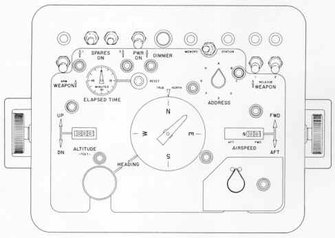
Figure 16; C-3313 CIC Control

Figure 17; CIC Control Panel


TRANSMITTER CONTROL (CIC)

The CIC transmitter control (figure 18-below) is similar in design and function to the deck transmitter control. Since it is installed below deck, it is not provided with a protective cover.

Figure 18; C-2804 Transmitter Control (CIC) Unit and Panel face

HEADING CARD ORIENTATION

    Aside from the absence of the maneuver stick on the CIC control, the principal difference between the CIC and deck controls is in the method or orienting the heading card. With the transmitter control power on, the heading card on the deck control (a ship compass repeater) is slaved to the destroyer gyro compass system. North (N) on the heading card will always point parallel to the destroyer gyro compass regardless of changes in destroyer heading. The pointer superimposed on the heading card indicates commanded drone heading at all times when the drone is airborne under deck control. As the destroyer maneuvers and changes heading, or as the drone changes its position with respect to the destroyer, the pointer display remains undisturbed relative to the heading card. Thus, the pointer and the fore and aft axis of the drone fuselage remain aligned at all times that the drone is airborne under deck control. If, however, the destroyer changes heading while the drone is on the deck, the true azimuth orientation of the drone also will change, but the pointer will continue to indicate the original true compass direction. In this instance, the heading pointer must be readjusted manually so that it is realigned with the drone true heading.

    The CIC control is mounted in a fixed position adjacent to the target display in the combat information center (CIC). The heading card is positioned so that its north always is aligned with the true north index on the case, which, in turn, is aligned with-true north indication on the target display. Thus, the CIC controller sees both CIC control heading card and target display in the same relative angular orientation.


OPERATING CONTROLS AND INDICATORS 

TRANSMITTER CONTROLS; DECK AND CIC

    The function of the controls and indicators on the deck and CIC transmitter controls, shown in figures 14 and 18, are listed in figure 19. The figure includes application code columns which relate the items to either or both transmitter controls. The power switches on the two controls are interlocked through a relay system to prevent the application of conflicting simultaneous commands from the two stations. The first station (deck or CIC) to turn power on has initial command authority. In a normal mission, the deck station power switch is turned on prior to CIC to establish initial command authority. When the deck power switch is turned off (with CIC power switch on), command is transferred from deck to CIC. Reversal of transfer is accomplished in a similar manner.


The panel nomenclature on these two units includes the abbreviation ADS, which means Air Defense Station. The Target Control System AN/SRW-4B does not include an Air Defense Station. ADS panel nomenclature should be interpreted (for destroyer use) as referring to the deck control station only.

Figure 19; DECK and CIC Transmitter Control Functions
(C-2801 and C-2804)

Control or Indicator

Applicable to

Function

DECK

CIC

PWR switch
X
X
Places both transmitter units (AN/URW-14A) (XMTR 1 and XMTR 2) in standby operation; also through relay interlock, determines deck or CIC command authority.
STBY indicator light
X
X
When lighted, indicates that transmitters 1 and 2 both are in standby operation and functioning correctly prior to application of high voltage.
XMTR 1 - XMTR 2 Switch
X
X
Selects the transmitter-coder combination to be used for the drone mission. Permits switch-over to the alternate transmitter and coder in the event of malfunction in the combination initially selected.
ADS 1 - ADS 2 Indicator lights
 
X
Indicates which of the two transmitter and coder combinations has been selected at the deck station.
CIC 1 - CIC 2 indicator lights
X
 
Indicates which of the two transmitter and coder combinations has been selected at CIC.
ADS OPERATE - CIC OPERATE indicator lights
X
X
Lighted according to sequence of operation of the power switches to indicate which station has command, and that high voltage has been applied to the selected transmitter.
HV switch
X
X
Controls the application of high voltage to the selected transmitter.
CARR. ON indicator light
X
X
Indicates that the selected transmitter is operating and supplying RF energy to the selected antenna.
ANT. SEL switch
X
X
Permits selection of either port or starboard antenna. 
PORT - STBD indicator lights
X
X
Indicates which antenna has been selected.
KEYED CARRIER-CONSTANT CARRIER switch
X
X
Permits selection of continuous or discontinuous transmitter output. In the constant carrier mode, the transmitter produces an unmodulated RF carrier output when no commands are applied, and a modulated RF carrier when commands are applied. In the keyed carrier mode, a transmitter output (modulated carrier) is produced only when an audiomodulating signal is being applied. (The QH-50D system operates only in the constant carrier mode.)
MODE indicator lights
X
X
Indicates whether the keyed carrier or constant carrier mode of transmission has been selected.
CODER EXTERNAL-INTERNAL switch
X
X
Permits selection of the external coder associated with each transmitter or a coder contained within the transmitter case. (The QH-50D system operates only within an external coder.)
EXTERNAL indicator light
X
X
Indicates that the external coder has been selected.
SIDE TONE receptacle
X
X
Permits audible monitoring of the operation of the transmitter.


CONTROL MONITOR

The function of the controls and indicators on the control monitor (figure 15) are listed in figure 20. The control monitor is located only at the deck station.

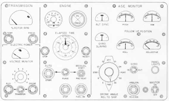
Figure 20; Control Monitor Functions 
(C-4298/ASW-20)

Control or Indicator

Function

MASTER switch
Applies 28 vdc to the circuits of the control monitor.
TRANSFER switch
Transfers power from the auxiliary motor-generator to the drone generator. AUX and DRONE indicator lights show which source of power is applied to the AFC set, according to the switch position. In the AUX position, the directional gyro slaves to the ship gyro compass. In the DRONE position, the directional gyro is connected into the AFC set.
VOLTAGE MONITOR meter and selector switch
Positions I through 9 monitor ac output of the auxiliary or drone generator and dc output of the power supplies in the AFC set. The meter indicates nominal voltage, with an acceptable +/- 5% variation. Position 10 is not used.
% ROTOR RPM meter
Provides a go no-go indication of proper rotor rpm by measuring drone generator output frequency. Dial markings indicate 95%, 100%, 105%, and 110%.
TEMP indicator light
Light goes on when transmission oil temperature is excessive.
PRESS indicator light
Light goes on when transmission oil pressure is inadequate.
EXH. TEMP meter
Indicates engine exhaust gas temperature as an average across the four engine thermocouples.
OIL PRESS indicator
Indicates engine oil pressure. Green lamp lights if engine oil pressure is in proper range. Red lamp lights if engine oil pressure is inadequate (below 30 psi).
ELAPSED TIME indicator and STOP and RESET switches
Starts when engine starting cycle is initiated. May be stopped and/or reset to 60 to monitor drone mission time.
ENGINE AUTO-PURGE- MANUAL mode switch
Permits selection of automatic or manual starting method. PURGE mode permits engine to be cranked with ignition system and fuel system disabled in order to clear burners of accumulated fuel following an abortive start.
AUTO START button
Initiates automatic starting cycle in which gas producer rotor cranking time and fuel valve opening are programmed automatically.
MANUAL starting switch
Provides non-automatic engine starting capability. The fuel must be turned on manually.
FUEL ON switch
Opens the fuel solenoid valve when the engine manual start cycle is used.
Engine STOP switch
Closes the fuel solenoid valve to stop the engine. Effective only while umbilical cables are connected. Can be used also to abort an automatic engine starting cycle.
ALT SYNC meter
Indicates that the barometric altitude control pickoff is nulled with the ambient barometric pressure. Synchronization takes place when the AFC set is operating from the auxiliary motor- generator (TRANSFER switch at AUX).
GYRO SLAVING meter
Indicates that the drone directional gyro system is nulled to a reference provided by the destroyer master gyro compass system. Slaving (alignment) takes place when the AFC set is operating from the auxiliary motor-generator (TRANSFER switch at AUX) and the directional gyro is electrically disconnected from the heading axis servo system.
DRONE ANGLE REL TO SHIP knob and pointer
Permits the drone directional gyro to be referenced to the destroyer gyro compass system regardless of the angle at which the drone is spotted on the deck. The pointer indicates the engine air inlet.
FOLLOW UP POSITION meters (PITCH, ROLL, YAW, COLLECTIVE)
Indicate direction and magnitude of displacement of the respective servo actuator output arms for given command inputs. Permit quantitative check of drone response to command inputs during prelaunch command tests.
GYRO switch
Permits roll and pitch gyro pickoff outputs to be removed electrically from the related servo system axes. When the switch is in the OUT position, the control system is unaffected by pitch and roll of the destroyer.
UMBILICAL RELEASE switch
Actuates the AFC set and engine umbilical connector release solenoids, disconnecting the umbilical cables from the drone. The power transfer and gyro disengage relays are interlocked with the separation of the AFC set umbilical cable connector for safety.
PANEL LIGHTS knob
Controls the level of panel illumination.


DECK AND CIC CONTROLS

The function of the controls and indicators on the deck and CIC control (figures 13 and 17) are listed in figure 21. The figure includes application code columns which relate the items to either or both controls.

Figure 21; DECK and CIC Control Functions
(C-3313 and C-3314)

Control or Indicator

Applicable to

Function

DECK

CIC

PWR
X
X
Energizes the panel lights, motor drive circuits, and the on-off function indicator lights. The interrogation pulses from the coder do not pass through this switch; thus, commands still can be applied with the switch in the off position.
CRUISE-MANUV switch
X
 
Determines mode of drone flight control. In the maneuver (MANUV) mode, the drone is controlled by the altitude knob and the maneuver stick. (Rotation of the maneuver stick energizes a motor which drives the heading knob. ) In the cruise mode, the drone is controlled by the altitude knob, the airspeed knob, and the heading knob.
STATION-MEMORY switch
X
X
In the station position, commands originating in the deck or CIC control direct the drone flight. In the memory position, the drone automatically retains its last commanded altitude, airspeed, and heading until control is returned to station.
HEADING knob and pointer
X
X
Commands and indicates drone fuselage heading. The pointer rotates with the knob to indicate commanded fuselage heading. At the CIC station, the heading card remains fixed with 0 at the TRUE NORTH index. At the deck station, the heading card remains slaved to the ship gyro compass regardless of ship heading.
Maneuver stick
X
 
In the maneuver mode only, controls the direction of the horizontal flight of the drone according to the direction of deflection. The drone flies in the direction of stick deflection regardless of the heading of the drone fuselage. When the stick is twisted clockwise or counterclockwise, it energizes an electric motor which drives the heading knob and pointer in the corresponding direction.
LATERAL TRIM
X
 
In the maneuver mode only, indicates the direction and exact magnitude of the roll command when the maneuver stick is displaced exactly perpendicular to the heading pointer. Pointer travel decreases as the deviation from perpendicular movement increases. Pointer remains at 0 when the maneuver stick is moved parallel to the pointer.
AIRSPEED knob and readout
X
X
In the cruise mode only, rotation of the knob commands forward or aft airspeed. The readout provides an approximate indication (in knots) of drone airspeed. True airspeed versus command readout data is shown in “Performance Data” section.
ALTITUDE knob and readout
X
X
Commands the flight altitude of the drone in both maneuver and cruise modes. The readout provides an indication (in feet) of the altitude commanded.
ALTITUDE RATE switch
X
 
Energizes a motor which drives the altitude knob and readout. The switch lever is spring-centered at neutral and is pressed upward to increase altitude or downward to decrease altitude. The switch also causes the pre- launch tie down device to be released from the drone when the lever is moved upward, provided that PWR switch is in the ON position.
ADDRESS selector switch
X
X
Selects three changeable bits in the message structure to synchronize the coder and decoder. The drone responds to commands only when the address selector switch setting matches the address setting on the decoder.
ELAPSED TIME indicator and RESET button
 
X
Starts when the CIC control power is turned on. May be reset to 0 by pressing the button to register drone mission time and to aid in maintaining a dead reckoning plot.
WEAPON ARM switch
 
X
Energizes the arming solenoids on the drone prior to re- leasing the weapon or weapons. Utilizes a two-way on- off channel, i. e., the weapons may be armed, then de-armed by returning the switch to its off position.
WEAPON RELEASE switches (1 and 2)
 
X
Actuate the bomb shackle release solenoids to release the weapons. The left-hand weapon is released by switch 1; the right-hand weapon is released by switch 2. A center weapon is released by switch 1.
WEAPONS JETTISON switch
X
 
Provides emergency weapon release capability at the deck station (Added to original components by Target Control System Change No. 14).
SPARES switches (1 and 2)
X
X
Actuate two on-off channels. Not connected in the present system.
ENG OFF switch
X
 
Initiates a drone shutdown sequence. When the switch is moved in the direction indicated by the arrow, the carrier and gyro signals are removed and the cyclic controls are driven to neutral, the control locks are engaged and the fuel is shut off. The airborne electrical circuit passes through the skid switches so that the engine cannot be shut off while the drone is airborne.
CABLE REL switch
X
 
Not used in the present system.
DIMMER knob
X
X
Controls the level of panel illumination.

End of Description Section


Home Up Description Normal Procedures Emergency Procedures Auxiliary Equipment Operating Limitations Flight Characteristics Systems Operation Crew Duties All Weather Ops Performance Data


Helicopter Historical Foundation
P.O. Box 3838, Reno, Nevada USA 89505

Because of SPAM, we ask that you copy the below address into your mail program and send us your comments!

Email us at: Gyrodyne_History@Yahoo.com

The name "Gyrodyne" in its stylized form above, is the Trademark of and owned by the Gyrodyne Helicopter Historical Foundation; unauthorized use is PROHIBITED by Federal Law.

All Photographs, technical specifications, and content are herein copyrighted and owned exclusively by Gyrodyne Helicopter Historical Foundation, unless otherwise stated.  All Rights Reserved ©2013.

The Gyrodyne Helicopter Historical Foundation (GHHF) is a private foundation incorporated in the State of Nevada as a Non-profit organization. 

GHHF is dedicated to the advancement of the education and preservation of the history of the Ships, the Men and the Company that built, operated and flew the U.S. Navy's QH-50 Drone Anti-Submarine Helicopter (DASH) System and to the preservation of the history of the U.S. Army's past use of DASH.
Your support will allow for that work to continue.