|
MINIMUM CREW
The minimum
crew required for the accomplishment of a drone mission from launching to
landing is the deck controller and the CIC controller. This assumes that the
drone has been spotted at the launch area and secured to the deck with a tie
down device which has a remotely actuated disconnect.
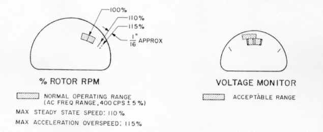
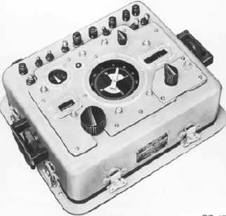
INSTRUMENT MARKINGS
All the instruments
used in the operation of the drone are mounted on the panel of the control
monitor. With the exception of the elapsed time indicator, these instruments
function only while the umbilical cables are connected to the drone and the
system is energized. The instruments serve to monitor drone readiness for
launching. Certain of the instruments provide a go no-go indication; the
remainder provides a quantitative indication. The instrument markings are shown
in figure 1 of this section and are explained, where necessary, in the following
paragraphs.
NOTE:
The follow-up position meters are not shown in figure 1 since their indications
are proportional to the magnitude of the command inputs. Refer to the section
“Normal Procedures”.
EXPLANATION OF INSTRUMENT
MARKINGS
ENGINE
EXHAUST GAS TEMPERATURE
Engine exhaust gas temperature will vary with ambient temperature. Refer to the "Performance
Data" section for charts of exhaust gas temperature versus ambient
temperature.
TRANSMISSION OIL
TEMPERATURE
The transmission oil
temperature indicator light goes on if the transmission oil temperature becomes
excessive. If the light goes on, stop the engine immediately, observing the
proper procedures described in the section “Normal Procedures”.
TRANSMISSION OIL
PRESSURE
The transmission oil
pressure indicator light goes on if transmission oil pressure is inadequate and
when the transmission is static. When the engine is started, the light should go
out within 35 seconds after the cranking cycle is started. If the light goes on
during operation, stop the engine immediately, observing the proper procedures
described in the section “Normal Procedures”.
VOLTAGE MONITOR
The
voltage monitor should indicate within the acceptable area at each of the switch
positions I through 9, except that on position 1, the indication may be to the
left of center. Position 10 is not used.
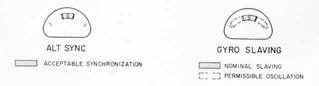
ALTITUDE CONTROL
SYNCHRONIZATION
The
altitude synchronization meter should indicate within the green band before
power is transferred to the airborne generator (control monitor TRANSFER switch
from AUX to DRONE).
GYRO SLAVING
The
gyro slaving meter should indicate within the green band or oscillate uniformly
and equally beyond each side of the green band (not hitting the stops) before
power is transferred to the airborne generator.
Figure 1: Instrument Markings
|
|
|
|
|
ENGINE LIMITATIONS
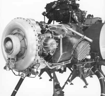 Engine output speed and power are controlled
within limits by the fuel control unit and the power turbine limiter. The power
output required of the engine is determined by the aerodynamic loading of the
rotors. Engine output speed and power are controlled
within limits by the fuel control unit and the power turbine limiter. The power
output required of the engine is determined by the aerodynamic loading of the
rotors.
Engine Fuel is grade JP-5, Specification MIL-T-5624.
Engine operating limits are shown in figure 2. The engine must
be sent to an overhaul facility if any of the following time, temperature, or
speed conditions occur:
1. Average Exhaust Gas Temperature (EGT)
exceeds maximum starting or transient temperature limit, as applicable.
2. Average stabilized EGT exceeds maximum
stabilized temperature limit more than five times.
3. Average EGT has exceeded the maximum
stabilized temperature limit by 30º F for more than five minutes.
4. Gas producer speed exceeds 40,200 rpm or
output shaft speed exceeds 7200 rpm (120%)
Parameter
|
Condition
|
Limits
|
Shaft horsepower
Interstage bleed valve active
Interstage bleed valve inactive
|
Military rated
Nominal available
|
330 at 90º F
365 at 59º F
300 at 90º F
330 at 59º F
|
Gas producer speed
|
Maximum allowable
|
40,200 rpm*
|
Output shaft speed
|
Nominal
|
6000 rpm (610 rotor rpm)
|
Engine Oil Pressure
|
Flight idle to rated power
|
30 psig, minimum
70 psig, maximum
|
Engine Oil temperature
|
Flight idle to rated power
|
250º F, maximum, out of cooler
|
Engine exhaust gas temperature
|
Transient Starting
|
1200º F, maximum
1270º F, maximum
|
Maximum allowable stabilized EGT
Interstage bleed valve active
Interstage bleed valve inactive
|
At Rated Power
|
Refer to "Performance Data" Section
Refer to "Performance Data" Section
|
* This parameter can be monitored only when the Engine-Rotor System Test
set AN/USM-202 is connected to the drone. Refer to the "Power Plant,
Fuel and Related Systems" handbook; NAVAIR 01-150DHC-2-4.
|
ROTOR LIMITATIONS
Within the flight
envelope, rotor speed is automatically maintained within fixed limits by the
engine control system and, in the event of rotor overloading, by an electronic
rpm cross-feed limiting system.
The
rotors are driven by constant mesh gearing by the engine power output section;
no clutch is provided. When the engine is started, the rotors are brought to
flight idle rpm within approximately 60 seconds.
If rotor speed exceeds 762 rpm (125 %) the rotor assemblies
must be sent to an overhaul facility for inspection for possible overstress.
AIRSPEED
LIMITATIONS
Airspeed limitations
are set forth under the paragraph headed MAXIMUM VELOCITIES in this section.
Except as otherwise
required during launching and landing, a forward true airspeed of 30 to 60 knots
should be maintained during ascents, and 40 to 60 knots during descents.
COMMAND INPUT
LIMITATIONS
MANEUVER
LIMITATIONS
Acrobatic flight with
the QH-50D drone is prohibited.
For
purposes of acceleration during launching and landing, the maneuver stick (in
the maneuver mode only) can provide command authority in excess of that normally
required for these purposes. Excessive deflection of the maneuver stick can
cause the drone to exceed its flight envelope airspeed limitations. Sudden
large reversals of stick deflection should be avoided. The danger
inherent in such practice increases when the drone is in the heavy weight
configuration. As the drone begins to respond to a large maneuver stick command
input, the command must be reduced smoothly until a steady state safe flight
attitude is attained. For all normal flight operations in the maneuver mode, a
maximum of approximately 30 percent of maneuver stick displacement from neutral
should be adequate.

If,
in emergency, it is necessary to exceed 30 percent of stick displacement, the
requirement for smooth, gradual movement of the stick becomes more critical.
In both the maneuver
and cruise modes, it is possible to apply simultaneous collective and cyclic
pitch command inputs of sufficient total magnitude to cause the power required
to exceed the power available. If this demand is maintained, engine and rotor
rpm will drop, and collective limiting will occur. It is not possible to
determine an absolute magnitude of command input at which this will occur, due
to the
contributory effects of ambient temperature, barometric pressure, and
drone gross weight. Airspeed and altitude commands must be coordinated smoothly
to prevent excessive collective limiting. High g-load maneuvers such, as rapid
changes in airspeed commands and sudden large changes in altitude command should
be avoided, except as required during launching and landing operations. Normal
operation in the maneuver mode should be limited to 300 yards, maximum.
HOVERING
LIMITATIONS
Hovering at zero airspeed requires more power
and consumes fuel at a greater
rate than does directional flight at low and moderate speeds. Under conditions
of high ambient temperature and/or low barometric pressure, in combination with
drone heavy weight configuration, prolonged hovering should be avoided.
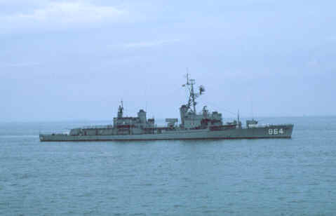
If
the drone is being hovered over the flight deck against a relative wind, it has
the advantage of the lift (or airspeed) proportional to the velocity of the
relative wind. In moving the drone away from the destroyer, this airspeed must
be maintained until the drone is clear of the destroyer, and then gradually
increased to move the drone upwind. In this manner, lift increases as the drone
moves out and a safe flight regime is maintained.
If
the opposite procedure is followed; i.e., if the airspeed required to hover over
the deck is reduced and the drone is allowed to drift down wind, the drone will
reach a point of zero airspeed, with respect to the surrounding air mass. As
this occurs, the power required increases, and, under marginal conditions,
settling will occur.
 HEADING
CHANGE COMMAND LIMITATIONS HEADING
CHANGE COMMAND LIMITATIONS
The turn rate of the
drone is inversely proportional to forward airspeed. When a large heading change
is commanded rapidly, the drone executes the turn; but, because its turn rate is
limited, it lags behind the heading pointer. Under certain circumstances, a
sudden reversal of the direction of turn will occur. The heading card is
provided with two diametrically opposed white sectors; one in the 0- to
90-degree quadrant, and one in the 180- to 270-degree quadrant. In commanding
turns greater than 90 degrees in which either a full white or a full black
sector will be spanned, the drone heading must occupy the sector being spanned
before the heading pointer is turned out of that sector. For example: if a turn
from 80 degrees to 190 degrees is to be commanded, the drone heading must
actually have passed 90 degrees before the heading pointer is turned past 180
degrees on the dial. Failure to follow this procedure will result in an
inadvertent turn reversal and may result in the loss of the drone.
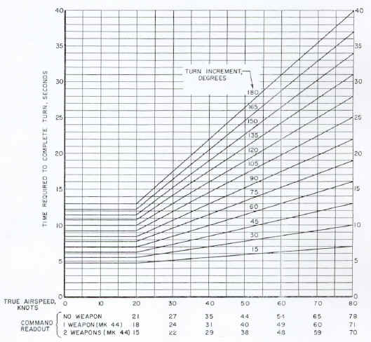 Figure
3, left, shows the calculated times required to complete turns as a function of
airspeed and turn
increment. This plot is based upon the turn rates programmed into the drone.
With a fixed bank angle in coordinated turns in the cruise mode, the turn rate
is automatically programmed to satisfy the turn coordination requirements. The
same turn rates apply when in the maneuver mode, even through the bank
angle is not present. Failure to observe the time limitations shown in figure 3,
prior to commanding a turn in the opposite direction, will result in a turn
reversal and may result in the loss of the drone. Deliberate heading command
reversals should be avoided. Figure
3, left, shows the calculated times required to complete turns as a function of
airspeed and turn
increment. This plot is based upon the turn rates programmed into the drone.
With a fixed bank angle in coordinated turns in the cruise mode, the turn rate
is automatically programmed to satisfy the turn coordination requirements. The
same turn rates apply when in the maneuver mode, even through the bank
angle is not present. Failure to observe the time limitations shown in figure 3,
prior to commanding a turn in the opposite direction, will result in a turn
reversal and may result in the loss of the drone. Deliberate heading command
reversals should be avoided.
The
phase of the roll signal in coordinated turns is related to the direction of the
change in drone heading; not to the forward or rearward movement of the drone
through the surrounding air mass. If, in rearward flight in the cruise mode, a
turn is commanded, the rotors will tilt in the direction appropriate to the
change in fuselage heading. In rearward flight the rotors will tilt toward the
outside of the turn, instead of toward the center and a mis- coordinated turn
will result. For this reason, while the drone is in rearward flight in the
cruise mode, turn commands must not be made.
 ALTITUDE
COMMAND RANGE ALTITUDE
COMMAND RANGE
The altitude
command capability of the shipboard guidance system is from -200 feet to +1000
feet. This range normally is directly related to the elevation of the operating
site; not to sea level. Thus, if the elevation of a shore based operating site
or fleet introduction site is 1000 feet above sea level, the operating range of
the drone, with respect to sea level, is 800 to 2000 feet. This characteristic
is due to the fact that the barometric altitude control synchronizes
(establishes its zero reference altitude), prior to launch, at the ambient
barometric pressure at the launching site.
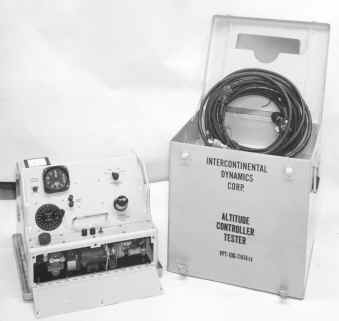
In making a shore to
ship transfer in which the sending station (shore based site) is more than 100
feet, but not more than 900 feet above sea level, the barometric altitude
control must be synchronized (zeroed) at an artificially induced static pressure
prior to launch. This operation requires the use of the Altitude Controller Test
Set VPT- 10G (seen above left). The procedure is described in the section,
“Normal Procedures”
under the paragraph headed TRANSFER, ALTITUDE TO SEA LEVEL.
Transfer from an
elevation greater than 900 feet to sea level cannot be accomplished with the
QH-50D system. Transfers from elevations greater than 750 feet must be
accomplished without weapons.
CENTER OF GRAVITY AND
WEIGHT LIMITATIONS
The center of gravity
and weight of the drone are fixed within a well-defined envelope because of the
limited number of variables, which are:
1. Fuel quantity remaining.
2. Number and type of weapons carried.
The average fore and
aft CG location has been determined to provide an adequate margin of
longitudinal cyclic pitch control in all weapon configurations. It is essential
that recommended weapon-loading procedures be adhered to and that no
unauthorized equipment be installed on the drone.

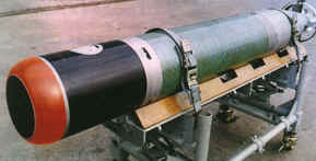
 General information on Mark 44 and Mark 46 torpedoes and
their accessories is contained in U. S. Navy Aircraft Torpedoes, Accessories and
Trajectory Data (NAVAIR OP 1207, Fourth Revision
with Change 1). The information contained in that publication relating to the
fore and aft positioning of the suspension bands is not applicable to the QH-
50D drone. The center gravity of the Mark 44 torpedo with Mark 24 air stabilizer
attached, and Mark 46 torpedo with Mark 31 air stabilizer attached, must be
located 2. 7 ±0. 25 inches forward of the mast centerline. (Refer to NAVAIR
01-15ODHC-2-1, General Information and Servicing, for weapon installation data
specific to the QH-50D drone).
General information on Mark 44 and Mark 46 torpedoes and
their accessories is contained in U. S. Navy Aircraft Torpedoes, Accessories and
Trajectory Data (NAVAIR OP 1207, Fourth Revision
with Change 1). The information contained in that publication relating to the
fore and aft positioning of the suspension bands is not applicable to the QH-
50D drone. The center gravity of the Mark 44 torpedo with Mark 24 air stabilizer
attached, and Mark 46 torpedo with Mark 31 air stabilizer attached, must be
located 2. 7 ±0. 25 inches forward of the mast centerline. (Refer to NAVAIR
01-15ODHC-2-1, General Information and Servicing, for weapon installation data
specific to the QH-50D drone).
Airspeed calibration
data (true airspeed versus command readout) for the various Mark 44 weapon
configurations is included in the “Performance
Data” section. Airspeed
calibration data for the drone with Mark 46 weapon store will be supplied when
available.
Automatic
compensation is provided for lateral center of gravity shift as one of two
side-by-side weapons is dropped. The compensation is inherent in the design of
the system; no weapon sensing devices are required. (Refer to “Flight
Characteristics” section)
The fuel tank is
close enough to the average center of gravity of the drone that the expenditure
of fuel has no significant effect on the flight characteristics of the
drone.
The drone is equipped
with mounting provisions for an operational telemetry package consisting of the
following components:
Telemetric
Data Transmitter T- 1014/AKT- 20
Multiplexer
TD- (TBA)/AKT-20
Fuel
Level Sensor DT-324/AKT-20
Five ballast weights,
fastened to the forward side of the avionic panel, must be removed when the
operational telemetry components are installed.
OPERATING ENVELOPE
The operating flight envelope is defined
below (Refer also to the “Performance Data”
section).
The
limitations set forth in the following paragraphs constitute the flight envelope
of the QH-50 drone in its configuration as of June 15, 1967. Any changes to, or
expansion of, the flight envelope will be set forth in subsequent revisions of
this section.
MAXIMUM VELOCITIES
The true airspeeds listed
below shall not be exceeded. Refer to the airspeeds calibration data in the
"Performance Data" section for the command readout required to produce
the desired true forward airspeed of the drone.
Direction and Configuration
|
True Airspeed
in Knots
|
Forward, all configurations
|
80
|
Lateral: Maneuver mode, all configurations
|
40
|
Rearward: Maneuver mode, all configurations
|
35
|
AVOID High G-Load Maneuvers in all
configurations and at all airspeeds.
ALTITUDE LIMITATIONS
ALTITUDE LIMITATIONS CHART
|
Within visual range of controller (actual)....
|
0 to 1000 feet
|
Beyond visual range of controller
(commanded)...............
|
300 to 1000 feet
|
Rate of change of command..............
|
300 feet per minute
(5 feet per second)
using the ALTITUDE knob; otherwise limited by the ALTITUDE RATE switch
|
AVOID abrupt altitude commands during
steady state flight conditions.
Do not exceed the 300-foot per minute rate of change of command, ascending or
descending.
WEAPON DROPS
 The
weapon drop envelopes shown in the “Performance Data” section are based
solely upon the requirements of the Mark 44 torpedo with Mark 24 Mod 2 air
stabilizer and Mark 46 torpedo with Mark 31 Mod 0 air stabilizer. The entire
envelopes shown in the charts may be used when the drone is within visual range
of the controller. When the drone is beyond visual range of the controller, a minimum
commanded altitude of 300 feet must be maintained,
due to the air speed versus altitude characteristics of the drone described in
the “Flight Characteristics” section. The
weapon drop envelopes shown in the “Performance Data” section are based
solely upon the requirements of the Mark 44 torpedo with Mark 24 Mod 2 air
stabilizer and Mark 46 torpedo with Mark 31 Mod 0 air stabilizer. The entire
envelopes shown in the charts may be used when the drone is within visual range
of the controller. When the drone is beyond visual range of the controller, a minimum
commanded altitude of 300 feet must be maintained,
due to the air speed versus altitude characteristics of the drone described in
the “Flight Characteristics” section.
DATA LINK CONTROL RANGE
Drone altitude
in feet
|
Range in
nautical miles
|
500
|
30.0
|
400
|
29.5
|
300
|
26.0
|
200
|
22.0
|
100
|
14.0
|
MISSION DESCRIPTION
The drone has the capability of accomplishing the mission
described below, based on normal gross weight at launch and 80 knots Vmax, to a
maximum combat radius of 40 nautical miles.
1. Warm up and launch in 1/2 minute
|
2. Cruise out at Vmax air speed
|
3. Loiter out of ground effect for 38 minutes
|
4. Cruise back at Vmax, retaining weapons
|
5. Land
|
Note: Refer to "Performance
Data" for fuel consumption and endurance data.
|
TURN LIMITATIONS
The maximum allowable single continuous turn in the cruise mode
is as follows:
At ambient temperatures of 65º F or
less, 0 to 80 knots, true airspeed..................180 degrees
|
|
|
At ambient temperatures greater than 65º F,
0 to 20 knots, true airspeed............45 degrees
20 to 80 knots, true airspeed.........180 degrees
|
In order to prevent turn reversal, turns exceeding 80 degrees must be
accomplished in successive command increments not exceeding 80 degrees for each
increment. The times required to wait between turn commands at various airspeeds
is a function of the turn rates programmed into the drone. The calculated times
required to complete turns, as a function of airspeed and turn increment are
shown in figure 3.
Any
single commanded incremental airspeed change of more than 30 knots requires a
minimum delay of 5 seconds before commanding a turn.
SHIPBOARD
OPERATING LIMITATIONS
Launches and landings should not be executed when deck motion exceeds a total
roll travel of 7 degrees and a total pitch travel of 2 degrees.
ROLL
AND PITCH GYRO HANDLING LIMITATIONS
During the time the roll and pitch gyro is running down (approximately 20
minutes), the drone should not be subjected to steady state motion about the yaw
axis at a rate greater than 60 degrees per second, or momentary motion about the
yaw axis at a rate greater than 200 degrees per second for more than 0.1 second.
WEATHER LIMITATIONS
Drone operations may be curtailed under adverse weather conditions at the
discretion of the operating activity.
End of Operating Limitations Section


|